Maximizing geological information from pressure tests and depth plots
Pressure-depth plots are powerful methods to visualize the wide array of industry pressure data and aid interpretation for safety, drilling, and exploration purposes.
Pressure-depth plots and complementary mud weight-depth plots communicate the data that are instrumental in making decisions in well control and casing design.
The rapid and flexible display of fluid and fracture pressures enables integration into exploration risking as well as testing fault seal integrity and assessing reservoir drawdown in development and production situations.
Other applications include:
• Evaluation of fluid type and hydrocarbon-water contacts, applicable to reserves estimation and valuation;
• Recognition of lateral fluid flow (hydrodynamics and tilted oil-water contacts);
• Assessment of trap breaching (seal integrity) and lateral transfer of deep overpressure to shallow zones (shallow water flows), reservoir connectivity, migration pathways, and basin modeling.
• Well planning and casing design, especially for high pressure wells.
Introduction
Drilling into sedimentary rocks while exploring for oil and gas must be done safely.
If the rocks are unexpectedly overpressured a serious and expensive influx can occur.
Apart from safety, high-pressure wells are expensive to drill. Understanding pressure data and overpressure in its regional geological context is crucial.
More than half of the world’s sedimentary basins drilled for oil, gas, and water contain at least some overpressured rocks. Examples include most deepwater regions, the Gulf of Mexico deep shelf gas play, subsalt plays (Gulf of Mexico, North Caspian, Red Sea); high pressure-high temperature areas (North Sea, mid-Norway) and Tertiary Deltas (Mississippi, Niger, Nile, Orinoco, Baram, Mahakam, etc.).
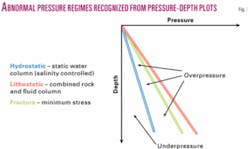
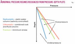
Overpressure occurs where pore fluid pressures exceed the hydrostatic pressure gradient (Fig. 1). The most common causes are the inability of fine-grained sediments to dewater during loading, diagenetic reactions of the shale matrix which transfer stress onto the fluid phase and fluid expansion especially associated with gas. Hydraulic head where aquifers are connected to highland areas and the buoyancy pressure in the petroleum phase in an accumulation also contribute to overpressure.
Underpressure is also recognized and exists when pressures are below hydrostatic pressure gradient (Fig. 1). This situation is attributed to differential recharge-discharge of reservoirs, deflationary pressures during elastic rebound on uplift, thermal convection, and/or reservoir drawdown and depletion.
Pressure data display, analysis, and interpretation can be vital at all stages of drilling in exploration, development, and production situations with implications for safety, well control-casing, and predrill exploration planning. Pressure-depth plots provide a fast, cost-effective method to visualize the data and aid interpretation.
Building a P-D plot
Combining pressures with depth on a pressure vs. depth plot (Fig. 1) offers the opportunity to determine:
1. Formation pressure with respect to hydrostatic pressure, i.e., determine if abnormal pressures exist;
2. Proximity of formation pressures to fracture and lithostatic pressures, i.e., assess potential for hydraulic fracturing and seal breach, and
3. To evaluate fluid density and type and establish fluid contacts, where appropriate.
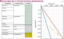
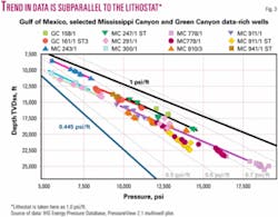
Once the lithostatic, hydrostatic, and fracture gradients have been defined from their respective data sources, pore pressure data (direct such as RFT, DST, and LOP and indirect such as mud weight or kick) can be visualized on P-D plots; either on a single well P-D plot with geological data displayed alongside (Fig. 2) or on a multiwell plot comparing values from two or more related wells (Fig. 3).
Pressure-depth (P-D) plots
On a single-well plot, display of stratigraphy (age data) and lithology (rock-type data) help in visualization of pore pressures in relation to the distribution of reservoirs and potential seals (Fig. 2).
Interpretation of pore pressure data is very difficult without its geological context. Location of changes in both pressure gradients and magnitude of abnormal pressure relate to changes in rock properties, primarily permeability, which can be linked to chronostratigraphy, and lithology.
For example, in Fig. 2 the principal reservoir sandstone of mid-Jurassic to Permian age below 14,000 ft has RFT data showing a hydrostat-parallel pressure gradient (indicating water) and a consistently high overpressure at about 3,400 psi. Above this reservoir is a series of pressure tests in the Cretaceous limestone that show increasing overpressure from top to base.
These tests indicate a pressure transition zone through the limestone, which may also involve the Late Jurassic shales (13,800-14,000 ft), in which there are no pressure tests.
Both single-well and multiwell P-D plots can facilitate identification of pore fluids and hydrocarbon-water contacts, lateral and vertical “seals,” and pressure compartments.
Multiwell plots are also used to examine relationships between data from two or more wells. Overlapping pressures from two or more wells, or pressures plotting on a common fluid gradient, are signs of interconnectivity of reservoirs.
The data from the deepwater area of Mississippi Canyon, Gulf of Mexico, show clear lithostat-parallel gradient and steeper-than-lithostatic gradients associated with water and hydrocarbons (Fig. 3). All pressures are substantially above the hydrostat indicating overpressures. The overall trend is one of increasing overpressure with increasing depth, a characteristic of deltas with rapid deposition rates.
Identifying fluids, contacts
Pressure gradients vary with fluid density.
Petroleum (apart from very heavy oil) has lower density than water and is therefore recognized on P-D plots by steeper gradients than in the underlying aquifer. Two (preferably more) direct pore pressure measurements are required to assess the fluids present in sediments where vertical communication can be reasonably assumed.
Water-wet sediments fall within the range of pressure gradients for fresh water to fully saturated brines (gradients 0.434 psi/ft to approximately 0.52 psi/ft for fluids with density range of 1.00 to 1.20 g/cc).
Exceptionally, heavier solutes (e.g., calcium chloride) provide even higher gradients, as high as 0.54 to 0.55 psi/ft. Fresh water gradients less than 0.434 psi/ft occur at depth in areas of high geothermal gradients since increasing temperature reduces density while higher pressures increase it.
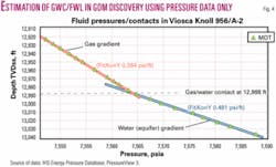
Gas gradients are most easily identified on single and multiwell plots (Fig. 4), while medium and heavy oil gradients can be quite subtle. Typical pressure gradients at standard temperature and pressure conditions for medium oils are 0.38 to 0.34 psi/ft (30-48º gravity) and for dry gases are 0.14 to 0.10 psi/ft. Wet gases-condensate gradients typically plot between gas and oil gradients.
At depth, densities are subject to change as they are controlled by ambient temperature and pressure conditions and linked to petroleum composition. This statement is especially true for gaseous petroleum, which is highly compressible. The approximate position of fluid contacts [pressure data actually indicate the position of the free water level (FWL)] can be determined from the intersection of fluid gradients (Fig. 4).
Pressure transition zones
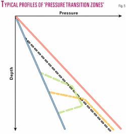
A pressure transition zone exists where the pressure interval gradient, as defined by two or more pressure measurements, exceeds the range of possible fluid gradients.1
Rocks preventing equilibration of fluid along a fluid pressure gradient cause a pressure transition zone, usually because the rock has relatively low permeability. Some authors refer to these zones as “pressure seals.”
The location of pressure transition zones and their gradients is controlled by (a) the mechanism creating the abnormal pressure, (b) the rock properties within the transition zone, and (c) the time period over which the nonfluid gradient pressure differences have been operating. The character of many pressure transition zones will change dynamically though time as a result of the evolution of fluid movement and pressure development of the basin in which they are found.
Progressive transition zones are found through shales in areas of rapid sedimentation (black line, Fig. 5), for example in Tertiary Deltas, the amount of overpressure captured by measurements in relatively thin, isolated reservoirs within the transition zone.
Sharp pressure transition zones (orange line, Fig. 5), for example at the base of the sandier section in the Gulf of Mexico deep shelf gas play, represent particular drilling challenges in terms of well control and casing design.
When lateral drainage occurs, overpressure reversals are found (green line, Fig. 5) usually involving deep, high-permeability units (sandstones, fractured carbonates) and associated faults and fractures that permit fluid escape to the surface.
Examples of reversals are found in the North Sea and Caspian Sea in regional sandstone reservoirs and in the Delaware and Anadarko basins in fractured carbonate.
Pressure compartments
Pressure compartmentalization of reservoirs involves restricted fluid movements over geological time. These “baffles” prevent equilibration of subsurface pressures along common fluid gradients. Compartments need to have effective baffles on all sides, i.e., so-called “top” and “bottom” seals as well as lateral barriers to fluid flow. The most common geological phenomena that create baffles are faults, facies change, caprock lithologies, and salt diapirs; the sealing character of these features may be aided by diagenesis.
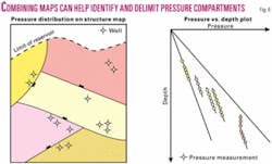
Multiwell P-D plots permit recognition of pressure compartments in the subsurface. Wells where the same magnitude of overpressure is found at a common reservoir-level are likely to be located in a shared pressure compartment (Fig. 6).
Different amounts of overpressure in the same reservoir in multiple wells indicate either the reservoir is compartmentalized by barriers (largely static) or the fluids are flowing from a higher overpressure region (dynamic system). A hydrodynamic system can be recognized where overpressures systematically change without the presence of barriers (e.g., continuous sand sheet), and can be proven where tilted petroleum-water contacts are found associated with common petroleum pressure gradients.
Identifying geological issues
Hydrodynamic traps
An open pore fluid system that is allowing an aquifer to drain is hydrodynamic until the pressures revert to the hydrostat (i.e., normal pressure condition).
Although associated mainly with highland recharge of an aquifer in an interior basin (e.g., US/Canada Alberta basin) hydrodynamic flow conditions are increasingly being recognized in overpressured sediments in which dewatering and coeval compaction are taking place to drive fluids towards the surface.2
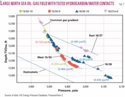
Hydrodynamic traps are recognized when a common hydrocarbon gradient is accompanied by several water gradients offset systematically across the base of the hydrocarbon accumulation.
Revisiting pressure data can help to identify fluid flow in a regional aquifer. Such fluid movement leads to tilted hydrocarbon-water contacts. A P-D plot based on data from Britannia field (UK North Sea) illustrates this distinctive pattern (Fig. 7). A combination of detailed reservoir structure maps and estimates of change in overpressure in the aquifer-reservoir system can be used to identify acreage where nonstructural traps might exist.
Seal integrity
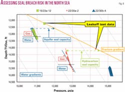
Pressure-depth plots can be used to assess the risk of seal integrity, i.e., when the seal may be breached by high pore fluid pressures causing fractures in the seal.
Hydrocarbon migration through a seal is a function of two main processes, i.e., (1) membrane leakage where petroleum buoyancy pressure exceeds the capillary entry pressure of the seal, and (2) hydraulic leakage through fractures-faulting generated as a result of high pore fluid pressures.
In a water-wet reservoir, the buoyancy pressure in the hydrocarbon phase has a minor influence on rock behavior, and hydraulic failure is most closely linked to aquifer pressure. It is therefore necessary to study both the aquifer and hydrocarbon seal capacity in order to assess seal breach risk (Fig. 8).
To assess seal integrity on P-D plots requires data to define fluid and fracture pressures. Fracture pressures and gradients can be derived from analysis of leakoff test data, which can then be compared with fluid pressures, derived from direct pressure measurements such as RFT, FMT, and MDT data, to analyze minimum effective stress and seal breach capacity (Fig. 8).
Fluid pressures that are close to the fracture gradient tend to occur where either a secondary overpressure mechanism operates (such as gas expansion) or where deep overpressures are conveyed to shallower levels, for example along a tilted reservoir.
Analysis of seal integrity helps in identification of “blown” traps (hydrocarbon leakage and remigration to a shallower level) but can be used, in combination with structure maps, to hunt for “protected traps,” i.e., those traps in which pore pressures will never reach conditions for hydraulic failure because they are hydraulically linked, through the reservoir, to a leak point. Such conditions are described from the Popeye-Genesis field area, Gulf of Mexico, by Seldon and Flemings.3
Fluid pressures close to the fracture pressure are observed in many other high-pressure environments, including several basins in Southeast Asia, the Central North Sea, Haltenbanken (mid-Norway), Trinidad, and the Nile Delta.
Pressure regressions
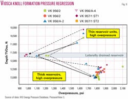
Pressure regressions are recognized on P-D plots when the magnitude of overpressure reduces with depth and can be illustrated on an overpressure-depth plot (Fig. 9).
Since overpressure describes the potential for fluid flow, and direction of flow is from higher overpressure to lower overpressure, pressure regressions are associated with dewatering from above and below the intervals of pressure regression. Pressure regressions are also evidence of lateral escape of fluids from beneath the shallower overpressure zone.
Lateral escape of fluids is usually associated with drainage though continuous reservoir packages extending to (a) the surface (e.g., Productive Series, South Caspian Sea), (b) near-seabed (e.g., Paleocene fan-sands, North Sea) or a combination of continuous reservoirs and linked faults/salt diapirs (e.g., Plio-Pleistocene, Gulf of Mexico).
Lateral drainage is a feature of many deltaic and fan-delta settings, and pressure regressions are a feature of the Nile Delta, offshore Egypt; Mahakam Delta off Kalimantan, Indonesia; and Mississippi Delta, offshore GOM (Fig. 9). Lateral drainage presents challenging demands on well casing design especially where the transition zone from higher to lower overpressure is sharp and associated with a large pressure difference.
Lateral transfer-centroid
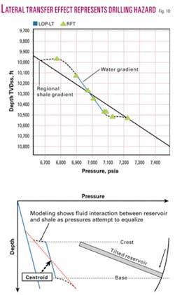
Lateral transfer is the focusing of fluids transferred from deep to shallow within a continuous, confined reservoir or other high permeability fluid pathway.4
The source of the pressure is likely to be overpressured shales surrounding the tilted reservoir. P-D plots assist in the recognition of lateral transfer, which represents a drilling challenge, since the reservoir and surrounding shales at the crest of the structure, where a well is most likely to be located, are not in pressure equilibration, except at the “centroid,” the point of pressure equilibrium between the shale and the reservoir (Fig. 10).
The effect of lateral transfer is to create higher overpressure at the reservoir crest relative to its expected value at that depth. Pressure-depth plots can be used (as shown in Fig. 10) to calculate this effect, a process that involves identifying the position of the centroid and extending a fluid gradient to the structural crest.
The crest pressure can then be compared to a regionally or locally determined “shale gradient,” although recognizing that there will be some attempt by the fluids in the reservoir to invade the shales around it, potentially reducing the effect. The centroid can be located higher or lower than the structural midpoint depending on a number of factors, including structural geometry, shale permeability, and depositional setting.
Lateral transfer and the centroid are particular challenges in regions where there is simultaneous sediment deposition and structural development, for example in salt-induced minibasins (e.g., Gulf of Mexico) and areas of growth faulting and reservoir rotation (e.g., offshore Texas; Niger Delta, Nigeria; offshore Trinidad).
Areas of early structural tilting, such as the high-pressure Jurassic and Triassic reservoirs of the North Sea, with multiple unconformities and later burial, experience only minor lateral transfer effects.
Mud density-depth plots
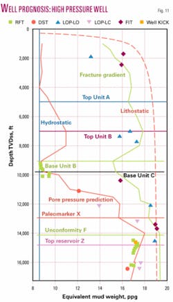
P-D plots are an essential part of well planning.
Well planning and casing design, however, are done using pressures expressed as equivalent mud weight (usually in pounds per gallon or specific gravity units).
Input required includes a prediction of pore pressure and fracture gradient, which are often supported by local data from offset wells (Fig. 11). Significant stratigraphic marker horizons may be added to illustrate the location of hydraulically connected units (same pressure regime) and pressure transition zones.
Note that with a plot of equivalent mud weight, the same overpressure requires less mud to balance the pore pressure with increasing depth, so a reservoir requires highest mud weight at the top (see offset data for Reservoir Z in Fig. 11).
Acknowledgments
Data displayed in the P-D plots were made available by IHS Energy from its North Sea and Gulf of Mexico Pressure Database. Thanks to Keith Howlett for comments on an early version. ✦
References
1. Swarbrick, R.E., and Osborne, M.J., “The nature and diversity of pressure transition zones,” Petroleum Geoscience, Vol. 2, 1996, pp. 111-116.
2. Dennis, H., Baillie, J., Holt, T., and Wessel-Berg, D., “Hydrodynamic activity and tilted oil-water contacts in the North Sea,” in Ofstad, K., and Alexander-Marrack, P., eds., “Improving the Exploration Process by learning from the past,” NPF Special Publication, 2000, pp. 171-185.
3. Seldon, B., and Flemings, P., “Reservoir pressure and seafloor venting: Predicting trap integrity in a Gulf of Mexico deepwater turbidite minibasin,” AAPG Bull., Vol. 89, No. 2, 2005, pp. 193-209.
4. Yardley, G.S., and Swarbrick, R.E., “Lateral transfer-a source of additional overpressure?,” Marine & Petroleum Geology, Vol. 17, 2000, pp. 523-538.
Bibliography
GPT/IHS, “North Sea Central Graben Pressure Study Non-Proprietary Report,” GeoPressure Technology and IHS Energy, 2004.
The authors
Richard Swarbrick ([email protected]) is managing director of GeoPressure Technology Ltd. in Durham, England. He has spent 26 years in the oil industry; 10 years with Mobil, 11 years in research and teaching, and the last 5 years as a consultant in pressures. He specializes in the geology of pressures and consults widely where traditional pore pressure techniques do not work well. He devised the PressureView software suite to visualize and interpret offset pressure data with their geological context and instructs on overpressure and pore pressure prediction.
Steve O’Connor ([email protected]) is a petroleum geologist with over 10 years experience in the oil industry. He started his career working on exploration assignments for Unocal and BP Amoco before moving to service companies to work in sedimentology-diagenesis in areas such as UKCS including Atlantic Margin and the Middle East. Lately he has become involved in fault seal analysis of reservoirs in UKCS, Gulf of Mexico, South China Sea, and East Africa as well as geomodeling and overpressure analysis.
Richard Lahann ([email protected]) is an independent consultant. He worked for Conoco for 23 years in the development and application of clastic diagenesis/reservoir properties and fluid/fracture pressure prediction and interpretation. He has maintained an active publishing record in clay mineralogy and clastic diagenesis. He continues to publish on the relationships between shale petrologic changes and fluid pressure generation.
