North Sea data yield insight on fatigue life of drill pipe
Failure of drill pipe due to fatigue is very costly problem in the oil and gas industry. Inspection costs represent a very small amount in well planning, and yet regular inspection intervals can significantly reduce fatigue problems.
Models used today can predict only about 20% of drill pipe life. Environmental conditions can change these predictions by significant amounts; predicted values seldom match with experimental values. This article provides an analysis of North Sea data regarding the effect of drilling parameters on the fatigue life of drill pipe.
Fatigue
Fatigue refers to changes in properties that can occur in metal due to repeated application of stresses or strains, although usually this term applies to those changes that lead to cracking or failure.1
The problem of fatigue increases during drilling of long and extended-reach wells. Despite several studies conducted of this subject, results seldom match with experience because the numerous drilling parameters vary considerably. Among those parameters, environment plays a vital role because it varies from well to well. The effect of severe environmental factors can cause sulfide stress cracking, hydrogen embrittlement, and corrosion of drillstring.
The variation of drilling parameters is not constant. These variations result in unexpected behavior of drill pipe. Although the effects of these variations are known, still unknown is the degree to which these variations affect drill strings. These variations usually lead to unexpected behaviors that often result in the failure of drillstrings.
Possible solutions to mitigate fatigue include design optimization of drillstring, better well planning, and improved inspection intervals. This article presents a statistical approach to design inspection intervals to avoid washouts. The effect of various drilling parameters on fatigue life of drill pipe is also investigated based on North Sea data.
Fatigue mechanism
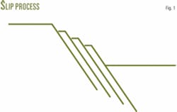
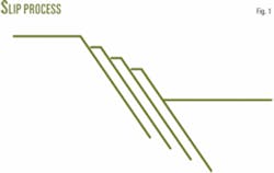
Iron has 24 different slip or deformation systems. This is twice the number found in most of the common metals. The slip mechanism is like shearing a deck of cards, in that one plane slips over another (Fig. 1).2
The slip process does not occur by whole one plane moving a distance of one atom over the plane below it, for this would require breaking all bonds over the whole slip plane at one time. Such a process would require about 1,000 times more shear stress than is required to cause slip in real crystals.2 The explanation for real behavior lies in the fact that crystals have imperfections, called dislocations. Crystals generally contain about 109 dislocations/cu cm.
If crystals were perfect, slip could only occur by shearing, and pure iron would have a yield of about 2 million psi. But, dislocations are metallurgical boundaries responsible for fatigue behavior. Work hardening of material is done so that these dislocations cannot move as easily as before. This type of material imperfection means that the smallest possible crack always exists at crystal scale. These imperfections grow at the atomic scale.
Whether the crack will propagate from inside or outside the pipe depends on the type of loading. If a specimen is work hardened, then there are more chances that a crack will grow from outside to the inside of the pipe because the outer fibers are in compression. If external stresses are applied, the imperfection will grow to an extent that the material will eventually fail. Therefore, the fatigue mechanism should be divided into two stages.
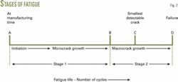
- Stage 1 growth. Due to cyclic loading, minute imperfections grow at different scales from crystal level to visibility. Physically speaking, these imperfections also act as stress concentrators but at undetectable levels. This is why, while estimating fatigue life of drill pipe, we cannot practically estimate about 80% of the actual life of the drill pipe (Fig. 2).3
- Stage 2 failure. Sudden fracture of the cross section occurs when a crack reaches its critical size. This size will vary with geometry, loading conditions, and material toughness. Point C in Fig. 2 represents smallest crack size detectable by inspection.
Fatigue models
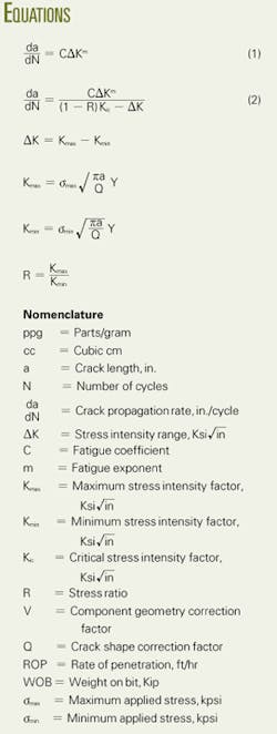
Various researchers have postulated that the growth of a crack under cyclic loading should be governed by Equation 1.1
The stress intensity range, ΔK, depends on crack shape, component geometry, stress applied, and minimum crack size. The empirical constants, C and m, are functions of material properties and microstructure, fatigue frequency, mean stress or load ratio, environment, loading mode, and stress state.
The Forman crack growth rate model is employed in this statistical approach to setting up the inspection intervals. This model is a modification of the Paris model. The Forman model also incorporates crack opening and closure during the application of cyclic stress cycles.4 The fatigue model is written as Equation 2.
Statistical analysis
It is impossible to predict the actual amount of stress generated in drill pipe, especially while drilling long, extended-reach horizontal wells. This is due to the conditions under which drilling takes place. Therefore, it is impossible to correctly predict the number of cycles before drill pipe failure.
It is common practice to report number of rotating hours of drill pipe in a well before it fails. This is also based on estimation. Certain oil companies are trying to install computerized chips on drill pipe that will record different drill string parameters such as cycles to failure, location of pipe, date last inspected, etc.5
The maximum operating stress for drill pipe is taken as 80% of the lower yield strength; minimum stress level varies from zero to the endurance limit. If a component is being operated at the endurance limit, it can have an infinite number of cycles to failure. This statement is the basis for Goodman curve.1
The endurance limit is usually 0.35% to 0.4% of yield strength. The minimum crack size should be the size that is not detectable by inspection methods used in the oil and gas industry. In this article, a semielliptical surface crack is assumed. The constants, C and m, were taken from the North Sea.6 Values for Kic can be found from literature. The load ratio R is 0.6.
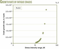
Fig. 3 shows a plot of stress intensity range and crack propagation rate. The relationship suggests that whenever a crack is formed in the drill pipe, it will grow at an exponential scale with a slope, m. The position of this line will be determined by the constant C.
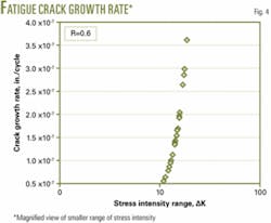
At higher stresses, it will grow at a faster rate, meaning that drillstring subjected to the higher stresses has greater probability of breaking off than washing out. A closer look at the lower stress intensity range shows that this crack will grow nearly vertically (Fig. 4). The negative aspect of this finding is that life of drill pipe will be shorter. The positive aspect is that after a crack is formed, it should be easier for inspection companies to detect the crack.
Based on the plot in Fig. 4, if drill pipe is stressed to its maximum limit and the bit is rotating at 150 rpm with a ROP of 70 fph, then it can drill 42,665 ft during the whole of its life. Therefore, inspection should be kept at economically feasible number of feet drilled. This work suggests that inspection should be done for every 35-40,000 ft drilled. This inspection interval should reduce washouts by more than 50%.
It should be noted that this inspection interval is limited to offshore environments typical of the North Sea.
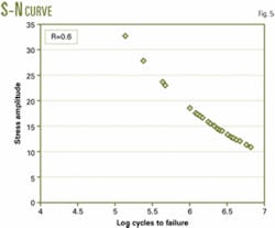
Fig. 5 shows an S-N curve for corrosive environment. The plot of this curve is determined by drilling conditions. This means that drill pipe will always remain at some stress level. The data suggest that drill pipe has a low endurance limit if it is operated in corrosive environments.
This reduced endurance limit can cause sudden failure of the pipe. Calculations can be done at the maximum stress intensity range and show that under a stress intensity factor of 32 Ksi √in, failure will occur after 13,293 ft. That is why under varying environmental conditions drill pipe can break at any point.
Crack growth
Different drilling parameters will affect the crack growth rate.
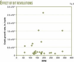
• RPM. Fig. 6 shows the effect of RPM on crack growth rate but not in a very descriptive manner. Apparently, RPM has no effect on crack propagation. Most points that have high crack growth rate have either high WOB or an excessive number of doglegs.
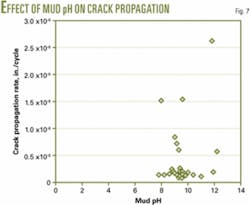
• pH of mud. Fig. 7 shows the effect of pH on crack propagation rate. It is evident from this plot that the pH of mud does not seem to have any effect as long as mud pH is in the range of 8-12. This result also confirms the finding of Azar that concludes that pH has no effect if drilling mud has basic nonacidic properties.7
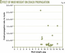
• Mud weight. Fig. 8 shows that the mud weight does not seem to affect crack propagation rate. By plotting such data, one can narrow the search to fewer suspect drilling parameters. Properly investigating these parameters will result in a better understanding of the fatigue life of drill pipe.
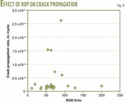
• Rate of penetration (ROP). Fig. 9 shows the effect of ROP on crack propagation rate, but the data present no discernible trend.
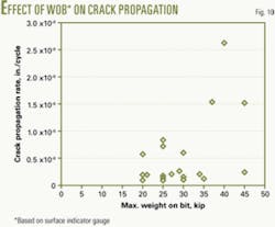
• Weight on bit (WOB). Fig. 10 shows the effect of WOB on the crack-propagation rate. This plot is interesting as it shows that having a high WOB can significantly increase crack growth rate. Note that longer number of rotary hours and even greater depths have been achieved by less WOB.
The physical understanding of higher WOB means that drillstring is subjected to more stress cycles. Microcracks in the string will fluctuate at a faster rate than before. This results in faster crack propagation. This is why washouts are often observed while back reaming-because high axial weight is being applied on the bit.
Hence, weight on bit is an important parameter during design of fatigue life of the components. The higher crack growth rate shows that time period from washout to break off will be shorter and eventually break off will occur before there will be a washout warning.
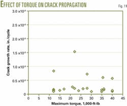
• Rotary torque. Fig. 11 shows that there is no effect of rotary torque on crack-propagation rate. This means that keeping WOB constant but applying more torque can result in achieving greater depths without increasing crack-propagation rate.
Next steps
There is no information about 80% of the life of a drill pipe. More research is needed to understand crack propagation from microlevel to visibility scale.
This analysis suggests a new inspection interval, based on Forman crack-growth model, that claims to reduce washouts by 50%.
It seems that various drilling parameters have almost no effect on crack-propagation rate. The WOB should not be increased, as more WOB will cause cracks to propagate faster. Greater depths can be achieved by applying more torque and constant WOB.
All studies have been done on S135 19.50 lb/ft, premium class pipe.
The data only represent North Sea failures.
Acknowledgments
Appreciation is due Maersk Oil and Gas (drilling department) for providing data and the suggestions and assistance of Andy Sloan, senior drilling engineer, Maersk Oil and Gas.
References
- Suresh, Subra, Fatigue of Materials, Second ed., Cambridge University Press, Cambridge, UK, 1998, 679 pp.
- Felters, Karl L., “The Nature of Fatigue,” Mechanical Engineering Aspects of Drilling and Production Symposium, Fort Worth, Mar. 23-24, 1964; published in Journal of Petroleum Technology.
- Metals Handbook, Ninth ed., ASM Intl., Materials Park, Ohio, Vol. 2, 1986, p. 102.
- Standard DS-1, Drill Stem Design and Operation, Third ed., T H Hill Associates Inc., Houston, January 2004.
- Nyen Twilhaar, G.D., and Hogen Esch, J.H.L., “Drill String Identification to Reduce Drill String Failures,” IADC/SPE paper 17210, IADC/SPE Drilling Conference, Dallas, Feb. 28-Mar. 2, 1988.
- Howard, J.A., Halbert, M.E., and Lubinski, Arthur, “Systematic Tracking of Fatigue and Crack Growth to Optimize Drill String Reliability,” IADC/SPE paper 25775, SPE/IADC Drilling Conference, Amsterdam, Feb. 23-25, 1993.
- Azar, J.J., and Lummus, J.L., “The Effect of Drill Fluid pH on Drill Pipe Corrosion Fatigue Performance,” SPE paper 5516, 50th Annual Fall Meeting of the SPE/AIME, Dallas, Sept. 28-Oct. 1, 1975.
Bibliography
Vaisberg, O., Vincke, O., Perrin, G, Sarda, J.P., and Fay, J.B., “Fatigue of Drill String-State of the Art,” Oil and Gas Science & Technology-Rev. IFP, Vol. 57, No. 1, 2002, pp. 7-37.
The author
Raja Hamayun Zafar ([email protected]) is working with Mærsk Oil and Gas on a drill pipe fatigue failure project. Zafar holds a BEng in mechanical engineering from UET, Lahore, Pakistan, and will complete an MSc (April 2007) in petroleum engineering at the Technical University of Denmark (DTU). He is a member of the SPE and SPE’s student chapter in Denmark
