Various recovery processes supply CO2 for EOR projects
Enhanced oil recovery (EOR) projects that use a carbon dioxide injectant can acquire CO2 using various processes that recover CO2 from industrial sources and produced gas streams.
With crude oil prices in excess of $30/bbl, both foreign and domestic projects are considering implementing EOR projects in aging oil fields. While most currently operating CO2 floods use natural CO2, some companies also are evaluating the possibility of obtaining CO2 from flue or industrial gas.
Recovery of CO2 from these sources has the added benefit of sequestering underground large amounts of CO2 that otherwise would vent to the atmosphere.
Enhanced oil recovery with CO2 is becoming economic in today's environment. Although CO2 recovered from flue gas is more expensive than CO2 from natural sources, it can still be economic for EOR projects. But because every EOR project is unique, each project requires a thorough study to determine the best gas-processing scheme and to evaluate the specific project economics.
CO2 supply
Nearly all CO2 EOR projects, most of which are in the US, use CO2 produced from reservoirs containing nearly pure CO2.
Many future CO2 flood projects will likely rely on various alternate CO2 sources as availability of natural CO2 decreases. Current prices for CO2 from natural sources vary between $0.75 and $1.25/Mscf, depending on location.
Industrial sources offer an alternative to naturally occurring CO2. For example, in 2002, the Weyburn project in Saskatchewan started injecting 95 MMscfd of CO2 recovered from the gas cleanup section of the Great Plains Synfuels Plant in North Dakota. Other industrial sources of CO2 include ammonia or hydrogen production facilities, where CO2 is a byproduct of the steam reforming and shift processes.
Recently, several oil companies have initiated studies to evaluate CO2 recovery from power plant stacks and other industrial sources.
Licensors of commercial processes to recover CO2 from either power boiler stacks or gas turbine stacks include Fluor Daniel (previously Dow Chemical Co.), ABB Lummus Global Inc.-Kerr-McGee Corp., Mitsubishi Corp.-Kansai Electric Power Co. Inc., and Praxair Inc.1-4
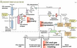
The flow scheme for all these processes is similar to amine units used to treat natural gas, refinery sour gas, or reformed synthesis gas (Fig. 1).
Most of these processes use an inhibited, 30 wt % monoethanolamine solution as the CO2 recovery solvent. The Mitsubishi process, however, uses a hindered tertiary amine solution.
The major challenge for implementing these technologies is to reduce capital cost and operating cost, especially energy consumption, so that the CO2 obtained is cost effective for EOR projects.
Technical challenges for these CO2 removal processes involve the control of corrosion and amine degradation. All of these processes employ a corrosion inhibitor and an amine reclaimer. Depending on the flue-gas source, the cost to remove soot, NOX, and SO2 can increase the cost of the facility.
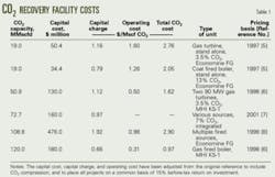
Table 1 presents reported capital and operating costs for CO2 recovery facilities. The cost data indicate that the price of recovered and compressed CO2 varies widely depending on the following factors:
- Plant capacity.
- Flue-gas source, such as coal-fired power plant, gas-turbine power plant, or industrial-fired equipment stack gas.
- Number of sources needed, the relative location of the sources, and the size of the sources.
- Extent of cleanup required upstream of the CO2 system.
- Type of facility, such as if the CO2 removal is a stand-alone process or part of an integrated facility, including power generation and CO2 compression.
- Value of fuel.
Flue gas project
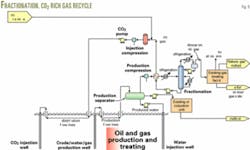
Fig. 2 shows an example of the process for recovering CO2 from stack gas within a complex that includes compression to deliver the CO2 by pipeline to injection compressors and CO2 pumps. In the oil and gas treating facility, the scheme removes CO2 from the produced fluid, enabling the recyling of the rich CO2 back into the reservoir.
The amine-based processes, previously discussed, can recover CO2 from the flue gases of boilers, gas turbines, or refineries. A large CO2 flood generally will require several CO2 sources, either from a single facility or several facilities. For multiple sources at a single facility, the installation may use a common amine regenerator.
Compressors typically deliver the CO2 to the pipeline at 1,500-2,400 psig. The delivery pressure usually is greater than the critical pressure of the CO2.
In the compression process, triethylene glycol (TEG) at a pressure of 500-1,000 psig is used to dehydrate the CO2 in order to eliminate possible corrosion problems in the pipeline that would be caused by wet CO2.
The CO2 pipeline may operate as a gas pipeline, or with CO2 as a supercritical fluid at a pressure greater than about 1,200 psig. Most large pipelines operate in the supercritical region.
Dehydrated CO2 pipelines are made from carbon steel and in the US, these pipelines must meet the regulatory requirements shown in 49CFR195 (Transportation of Hazardous Liquids by Pipeline; CFR = Code of Federal Regulations).
Most projects collect the CO2 at a central location at which the CO2 can be further compressed to the required pressure that achieves CO2 miscibility with the reservoir fluids. This pressure is known as the minimum miscibility pressure.
If CO2-rich gas recovered from the produced oil is recycled, then this gas is combined with makeup CO2 at the suction of the injection compressor. If the incoming CO2 is above the critical pressure, it is possible to pump the supercritical CO2 to injection pressure.
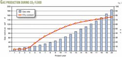
A combination of new and existing production wells and gathering lines normally are used for the produced oil and gas from the flood. The CO2 content of the produced gas may increase from an initial value of 1-5 vol % CO2 to more than 80% CO2 during the course of the EOR project.
The facility design needs to check the wellbore and collection headers and mains for this additional capacity. The increased CO2 content also can affect dramatically the corrosion rate in the well assembly, choke, and distribution lines. The project may need to replace some of these components.
The existing oil and gas separation equipment may or may not be adequate for the increased gas flow and higher CO2 content resulting from the CO2 flood. The project may require additional equipment for handling the higher gas flow rate and for processing the higher CO2 content gas.
CO2 content and total flow rate will increase dramatically in the associated gas during the course of the EOR project. Fig. 3 illustrates this change in a hypothetical project. These changes can greatly affect downstream gas processing, therefore, the facility design must evaluate carefully the equipment for capacity and flexibility to process the new gas composition and rates. Also, the design process must review the materials of construction for suitable corrosion resistance.
Downstream facilities
Options for further processing of the produced associated gas depend on the nature of the existing processing facilities, and the expected amounts of CO2, methane, and NGL gas during the life of the EOR project and the available NGL market. The most common options include:
Using the existing gas processing facility if enhanced production is only a small portion of the total production processed in the treatment plant, or during the early stages of the project before the CO2 breaks through to allow a staged investment.
Recycling associated gas back into the formation along with fresh CO2 injectant. The recycle design minimizes impacts on downstream processing facilities, and minimizes the volume, and therefore cost, of fresh CO2 injectant. This option is suitable if the combined injectant concentration with recycle is about 90-95% CO2; otherwise, the minimum miscibility pressure (MMP) might be higher than the reservoir pressure.
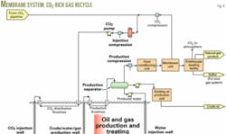
Processing associated gas in a membrane system to produce a CO2-rich stream for recycle with fresh CO2 injectant. This option may affect capacity in downstream facilities because this design does not remove significant hydrocarbon liquids from the associated gas. But this scheme provides a cost-effective way for providing a quality miscible injectant while minimizing the impact of CO2 on downstream processing facilities.
Two disadvantages of membranes are:
1. High power requirements because of the need to compress the entire associated gas stream for processing in the membrane unit and then recompressing the CO2 permeate.
2. Possible problems with hydrocarbon condensation in the membrane system at high CO2 concentrations.
Simple fractionation of the associated gas to produce a CO2-rich bottoms product stream for recycling and combining with fresh CO2 injectant. The overhead stream, which is a light-hydrocarbon stream, will contain a significant amount of CO2 due to the limitations of the single fractionator scheme, but the impact of this CO2 on downstream facilities must be considered.
This scheme involves recycling the hydrocarbons heavier than ethane along with the CO2 injectant. These hydrocarbons will not go to the gas-processing system for recovery. Again the combined injectant must be 90-95% CO2; otherwise the MMP might be greater than the reservoir pressure
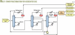
A multitower fractionation system to produce high-purity CO2 for recycle with fresh injectant, a methane-rich product, and an NGL product. This design is an economic alternative when NGLs have a significant value and gas-processing facilities are limited.
A two-tower arrangement can be used for sweet gas while a three-tower arrangement with NGL sweetening is needed for sour systems.
Figs. 2, 4, 5, and 6 show these process options.
Corrosion
Wet CO2 is corrosive to carbon steel. Strategies for minimizing corrosion include:
- Keeping CO2 concentrations, therefore partial pressure as low as possible.
- Dehydrating wet CO2 streams to remove water.
- Using corrosion inhibitors.
- Providing corrosion-resistant materials of construction.
The construction material for compressor discharge coolers and drums must be of stainless steel in all compression steps upstream of dehydration.
Dehydrated pipeline quality CO2 is noncorrosive; therefore the pipeline can be constructed of carbon steel. Special soft goods are required in shutoff valves and relief valves to ensure that explosive decompression will not occur upon depressurization.
CO2 corrosion of carbon steel can occur if there is gaseous CO2 when free water in a liquid phase is present, or where there is dissolved or free CO2 in a crude oil-water emulsion system. The primary factors that increase the CO2 corrosion rate are increasing partial pressure of CO2 and higher temperature (at least up to 160° F.). Corrosion inhibitors will substantially reduce the corrosion rate for carbon steel in the presence of wet CO2.
Inhibitors are most effective in pipelines and gathering systems in which it is easier to coat the walls effectively.
The design of a CO2 flood of an existing field must evaluate carefully all components of the production wellheads, gas-oil-water gathering trunk lines, production separators, and gas treating equipment.
Project economics
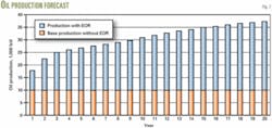
As an example, a hypothetical project proposes to increase oil production to 37,000 from 10,000 b/d, recovering an additional 150 million bbl of oil during a 20-year period. Fig. 7 shows the assumed crude oil production.
During the 20-year period, the project expects associated gas production to increase to 185 from 10 MMscfd, while CO2 content of the associated gas increases to 80% from 4% (Fig. 3).
This example assumes an injection of 200 MMscfd of CO2 (10 Mscf/bbl) throughout the project to obtain this additional oil recovery.
By year 20, the CO2 recycle from the associated gas can supply nearly 75% of the CO2 required.
The CO2 capture plant capital costs about $400 million. This could include up to four 2,600-tonness/day trains if the flue gas is gas turbine exhaust.
The example assumes an operating cost of $1/Mscf, which is consistent with the published data, and a $75 million, 50 mile, 20-in. pipeline for transporting recovered CO2 to the oil field.
The cost of CO2 injection wells varies significantly among projects, depending on the number of existing wells that can be converted to CO2 injection, the maximum capacity of new injection wells, well depth, and field location. Well costs can vary from less than $1/bbl to more than $10/bbl of produced oil. This analysis excludes these costs because they are variable and depend on a particular project.
This example assumes a simple recycle of the associated gas (Fig. 2) because of the low flow rate of the associated natural gas from this field and the ability to recycle without dramatically affecting the CO2-rich injectant miscibility pressure.
The cost of recycle compression for the associated gas is $50 million, which can be staged. Pumps at the distribution trunk line will increase the pressure of the combined recycle gas and makeup CO2 to 3,000 psig in order to overcome the reservoir pressure. The CO2 injection pump system has a $10 million capital cost.
The production portion of the EOR project will require material of construction upgrades because of the increasing CO2 content as the flood progresses. The production well tree valves will need replacement with valves of other material. In addition, the project requires new stainless-clad production flowlines.
While these costs can vary among projects, depending on the number and size of the production lines, this example will use a $100 million cost.
The analysis uses a 15% before-tax return on capital for all aspects of the project and a 20-year project life. Based on these assumptions, the example project requires a $29.20/bbl crude oil price to achieve a 15% before-tax return on investment, excluding the cost of new wells.
A higher crude oil price will increase the return on investment.
If a merchant source supplying several buyers supplies the CO2, then the project only will need to pay for the quantity of CO2 it uses. A $1.90/Mscf CO2 price for CO2 delivered to the pipeline at 2,000 psig will provide a 15% before-tax rate of return on the CO2 recovery facility. Using this price, the example project requires a crude oil price of $25/bbl to achieve a 15% before-tax return on investment, excluding the cost of new wells.
If the CO2 was available from natural sources at a typical price of $1/Mscf for CO2 delivered to the pipeline at 2,000 psig, then the sample project requires a crude oil price of $16.30/bbl, again excluding any injection well cost.
The cost of CO2, CO2 pipeline distance, the number of new wells required, and the extent of facility modifications needed greatly affect the project economics. In addition, cash-flow considerations decrease the project's economic viability because substantial capital investment is at the front-end while the economic benefits are at the back end of the project after the reservoir production responds to CO2 injection and after a significant amount of CO2 can be recovered from the associated gas. F
References
1. Reddy, S., et al., "Fluors Econamine FG Plus Technology—An Enhanced Amine-Based CO2 Capture Process," Second National Conference on Carbon Sequestration, Alexandria, Va., May 5-8, 2003.
2. CO2 Recovery from Flue Gas/ Turbine Exhaust Gas, ABB Lummus Global.
3. Mimura, T., et al., "Development and Application of Flue Gas Carbon Recovery Technology," Fifth International Conference on Greenhouse Gas Control Technologies, Cairn, Australia, Aug. 13-16, 2000.
4. Chakravarti, S., et al. "Advanced Technology for the Capture of Carbon Dioxide from Flue Gases," First National Conference on Carbon Sequestration, Washington, DC, May 15-17, 2001.
5. Chapel, D.G., and Mariz, C.L., "Recovery of CO2 from Flue Gases: Commercial Trends," Canadian Society of Chemical Engineers Annual Meeting, Oct. 4-6, 1999.
6. Iijima, M., "A Feasible New Flue Gas CO2 Recovery Technology for Enhanced Oil Recovery," Paper No. SPE 39686, SPE/DOE Improved Oil Recovery Symposium, Tulsa, Apr. 19-22, 1998.
7. Slater, M., et al., "Carbon Dioxide Capture from Multiple Flue Gas Sources." 6th Annual International Conference on Greenhouse Gas Control Technologies, Kyoto, Japan, Oct. 1-4, 2002.
8. Simmonds, M., et al., "A Study of Very Large Scale Post Combustion CO2 Capture at a Refining & Petrochemical Complex." 6th Annual International Conference on Greenhouse Gas Control Technologies, Kyoto, Japan, Oct. 1-4, 2002.
The authors
Barry Friedman ([email protected]) is a consulting process engineer with Washington Group International in Denver. He has more than 30 years' experience in implementing and supervising process design for natural gas, and refining projects. Friedman has a BE in chemical engineering from the City University of New York. He is a registered professional engineer, a member of the API Pressure Relief Systems committee, and a member of the Gas Processors Association.
Dick Wissbaum is a consulting process engineer with the Washington Group International. He has expertise in the design of gas-oil processing units, natural gas treating systems, sulfur recovery plants, and refinery fractionation systems. Wissbaum has a BS in mathematics and chemical engineering from the Colorado School of Mines. He is a registered professional engineer, and a member of the Gas Processors Association.
Shaun Anderson is a process engineer with the industrial process division of Washington Group International, specializing in design of oil and gas facilities. Anderson holds a BS in chemical engineering from the University of Colorado.


