Subsidence modeling for fluid reservoirs aids hazard mitigation
Karsten Zimmermann
Ralf Fritschen
DMT GmbH & Co. KG
Essen, Germany
Krzysztof Tajdus
Anton Sroka
Rafal Misa
Strata Mechanics Research Institute of the
Polish Academy of Sciences
Krakow
Subsidence prediction in fluid reservoirs is more difficult than in coal, salt, or ore deposits. Reservoir geometry, physical-mechanical rock mass parameters, and pressure distribution have more uncertainty in oil and gas reservoirs, resulting in a predicted subsidence range rather than a precise subsidence map.
Knowing the expected subsidence range and its related probabilities is mandatory for protecting surface infrastructure near the producing reservoir.
Strata movement
Oil and gas production-induced ground and strata movements can affect the surface in various ways, impairing or damaging buildings, industrial plants, or transport infrastructure. Subsidence can also induce undesirable hydrological changes including water stream disorders and shifting water-pipe grades.
Induced strata deformations can hurt oil and gas operations by altering production and injection wells or damaging integrated subsurface equipment. Subsidence can also alter the general landscape of a region.
This article introduces a subsidence model capable of predicting the size and type of ground movement in a reservoir. The model is based on the stochastic approach, including a parametrization following the Ruhrkohle method.1 2 The method was adapted for oil and gas reservoirs by integrating additional model adjustments and improvements.3 4 The model incorporates reservoir features, production data, geologic information, and in situ measurement data to predict temporally and spatially dense ground movement information. Data integration links the characteristics of the reservoir, oil and gas production, and observed movements, resulting not only in a complete three-dimensional description of surface and strata movements but also a way to calculate deformations at any point in time.
Based on the subsidence model, hazardous and damaging effects can be predicted and assessed for wide areas on the surface, classifying surface objects in terms of their induced-movement sensitivity. Large-scale assessment of subsidence areas can be performed with easy to apply criteria.5 For each sensitivity class, the maximum allowed object stress is defined with specific limit values for tilt, curvature, and extension-compression. Compliance with these values ensures effective protection for each object. Complex objects, such as industrial plants, wells, and underground infrastructure require specific studies to assess individual sensitivity to strata deformation.
Modeling ground movements
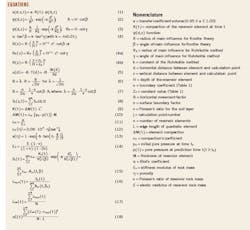
The defect volume of an underground element corresponds to the distribution of subsidence at surface, according to the theory of stochastic media. This relation is compatible with the transformed Gaussian function. Equation 1 determines the relationship in an element of fluidized deposits between the elementary volume defect, i.e., the compaction induced by reservoir pressure reduction, and the ground's surface subsidence (see nomenclature box).
This transfer influence function is based on the Gaussian influence function and may be represented by the Knothe theory (Equation 2) or the Ruhrkohle method in Equation 3.2
The presented methods differ in the main influence angle definition, but both provide identical results when the dependencies between the angles of influence β and γ are described by the formula in Equation 4. Equation 4a presents two methods to describe the radius of mining exploitation in rock mass R(z), or RK(z) above the extracted seam.
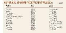
Equation 4b is modified to meet the initial condition for z = 0 (Table 1).6
Previous analysis and measurements have shown that the angle of influence for a sandstone with 20% porosity does not exceed 20°. The Groningen gas field in northeastern Netherlands has an estimated angle of influence of 7-11°, compatible with poroelastic model observations.7
In addition to subsidence prediction, the presented method allows for calculation of horizontal displacements and their derivatives, horizontal strains. The horizontal movement vector is proportional to inclination vector T (Equation 5).
Equation 6 represents the value of horizontal movement B, valid for solving ground movement problems in coal mining.11 Theoretical calculations for an elastic medium show the value of horizontal displacement coefficient B can also be described by Equation 7, for small and slowly growing deformation in the range of 0.10 to 0.15.6 8
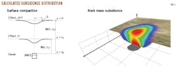
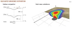
Fig. 1 shows subsidence values in a schematic cross section with a 3D visualization of the calculated subsidence distribution inside a rock mass and on its surface.12 These values are relevant for calculating the subsidence induced by one reservoir element, i, on calculation point j, which can be below or at the surface. An entire reservoir's subsidence can be calculated by discretizing the formation into finite elements and then superposing the individual subsidences (Fig. 2). Equation 8 shows this method of linear superpositioning. The summation of single subsidence influences will result in a joint general reservoir subsidence.
The discretized model-based description of the rock mass compaction is based on reservoir elements defined by location, volume, porosity, and pressure state.
Fig. 3 is an example of a reservoir discretization, presenting in detail the specific distribution of porosity and pressure changes in each element (Fig. 3a and 3b). Reservoir attributes necessary for modelling are often derived from borehole measurements.
Using the presented model, Equation 9 calculates the compaction volume, K(t), for each element. In addition to subsidence, further movement values such as slope, curvature, displacement, and strains can be derived and calculated. These calculations are especially relevant for estimating hazards and influences and the potential mitigation of these effects over time.
Compaction estimation
Equation 10 estimates the value of element compaction, ΔM(t), for a linear elastic model. The parameters p0, p(t), and M in this equation are typically estimated from in situ tests or measurements. The compaction's coefficient, which characterizes the deformability of the rock mass, is more difficult to estimate. This coefficient can, however, be determined by in situ rock tests. Equation 11 provides a rough formula for determining the coefficient in situations where such tests can't occur.
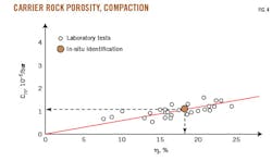
Compaction coefficient analysis, cm, shows its strong dependency on rock mass porosity, and in situ tests of sandstones near an oil field have confirmed a linear relationship (Fig. 4).9 10 Equation 12 represents the compaction coefficient for a sandstone with a constant 18% porosity. Table 2 presents different examples of compaction coefficients and porosities. Equation 13 determines the Biot coefficient, incorporating two parameters: α and Es.11
The presented solution shows that a worst-case scenario is applied when calculating oil production-induced deformation of the surface and rock mass, where Biot coefficient α = 1.0.
Calculating the compaction coefficient (Equation 11) requires knowing the reservoir rock mass's stiffness modulus. Because elastic modulus (E) and Poisson's ratio (v) tests are more frequently applied than stiffness modulus tests, this input can be problematic. Equation 14 can estimate the Es value if stiffness moduli are unknown.
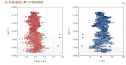
Despite this step, rock mass properties' values are difficult to estimate for the entire reservoir given the dimensions of and variable conditions within the rock mass. Rock mass tests help estimate the possible value range. Fig. 5 shows the test results for a 500-m thick oil reservoir rock mass. Its elastic properties were obtained via boreholes. The oil company confirmed the results with additional triaxial laboratory tests on 17 core samples, taken from depths of 2,250-2,650 m. These tests confirmed the value ranges for elastic moduli of 38.4-46.2 gigapascal (GPa) and for Poisson ratio of 0.109-0.169.
Variability in both parameters E and ν (Fig. 5) and porosity made determining compaction value cm extremely difficult. Moreover, fluidized deposits of raw material are characterized by highly variable spatial geometry. Boundaries are sometimes difficult to establish. The distribution of reservoir pressure must also be known to determine compaction value. All these elements are relatively difficult to evaluate, making calculation of the compaction value for individual elements in the subsurface uncertain. This uncertainty also applies to the transforming function's angle β, which depends on the properties of the rock mass between a fluidized bed and the surface. The parameters cm and β can, however, be determined with much higher precision using the method of identifying parameters, which is based on in situ subsidence measurements.
Model adjustment, calibration
Identification of the subsidence model's parameters can be carried out using either an exact or an approximate method. The exact method is based on the Gauss-Markov algorithm. The approximate method is related to the identification of subsidence model parameters in conjunction with the exploitation of coal. Modifications and adjustments allow this method to identify the parameters for exploitation of fluidized beds as well.
The starting point is Equation 15, which connects the measured subsidence of the j observation point at time t with the subsidence model of this point.
An iterative process will determine the likely value of cm and β, using a gradual changing value of β. Equations 16-18 calculate the data for β = βk (k = 1) given a constant value for the compaction factor of the entire deposit.
Equation 16 describes an average value of the compaction factor assuming β = βk and Equation 18 is the variance of the calculated set cmj k(t). From the relationship betweenThe value cm is determined directly from Equations 16 and 17 for β = βk or graphically, using the relationship between cm k(t) and β (Fig. 6b).
Numerical programs can identify the parameters of the subsidence model based on measured subsidence values.
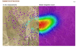
Fig. 7 illustrates data integration and subsidence modelling. The model is calibrated with sparsely distributed measurement points. The resulting modelling output delivers a dense pattern with information about subsidence and other important ground movement elements. Furthermore, using reservoir pressure variations allows prediction of future ground movements.
References
1. Knothe, S., "Subsidence trough profile formulas (in Polish)," Archive of Mining Science, Vol.1, No.1, 1953.
2. Ehrhardt, W. and Sauer, A., "The prediction of subsidence, imbalance and curvature over mining in shallow storage," Hubener, 1961, p. 15.
3. Sroka, A. and Tajdus, K., "Determination of surface subsidence above underground oil and gas exploitation (in Polish)," Drilling-Oil-Gas, Vol. 26, AGH Krakow, 2009.
4. Sroka, A. and Hejmanowski, R., "Subsidence prediction caused by the oil and gas development," 3rd International Association of Geomorphologists FIG Symposium, Baden, Austria, May 22-24, 2006.
5. Budryk, W. and Knothe, S., "The impact of underground mining on the surface from the point of view of securing facilities," Ref. Of the Congress of Sciences. Krakow, 1956.
6. Drzezla, B., "The variation of the angle of influence within strata (in Polish)," Mining Reviewer, No. 10, 1978.
7. Geertsma, J., "The analysis of surface subsidence resulting from gas production in the Groningen area, the Netherlands," Verhandelingen van het Koninklijk Nederlands geologisch mijnbourkundig Genootschap, 1973, p. 109.
8. Sroka, A., Knothe, S., Tajdus, K., and Misa, R., "Underground exploitations inside safety pillar shafts when considering the effective use of a coal deposit," Mineral Resources Management, Vol. 31, No. 3, December 2015, pp. 93-110.
9. Van Kesteren, J., "Estimate of compaction properties of Groningen reservoir rock," Verhandlingen Koniklijk Nederlands Geologisch Mijnbouwkundig Genootschap," Vol. 28, 1973, pp. 33-40.
10. Teew, D., "Laboratory measurements of compaction properties of Groeningen reservoir rock," Verhandlingen Koniklijk Nederlands Geologisch Mijnbouwkundig Genootschap, Vol. 28, 1973, pp. 33-40.
11. Fabre, D. and Gustkiewicz, J., "Poroelastic properties of limestones and sandstones under hydrostatic conditions," International Journal of Rock Mechanics and Mining Sciences, Vol. 34, No. 1, January 1997, pp. 127-134.
12. Zimmerman, K. "Modelling and data integration to determine ground and strata deformation over oil and gas reservoirs," 12 Geokinematischer Tag, Freiberg, Germany, May 5-6, 2011.
The authors
Karsten Zimmermann ([email protected]) is head of the Expert Body for Ground Movements and deputy head of the Business Segment Surveying and Geomonitoring at DMT GmbH & Co. KG in Essen, Germany. He is working in the field of geotechnical monitoring and leads commercial projects for the raw materials and infrastructure industry as well as various research activities on international scale. He holds a PhD and MS in mine surveying from TU Bergakademie Freiberg, Germany, and is a member of the International Society of Mine Surveying (ISM) and German Mine Surveyor Association (DMV e.V.).
Ralf Fritschen ([email protected]) is head of the Business Segment Surveying and Geomonitoring at DMT GmbH & Co. KG in Essen (Germany). He has been working on cause and effect of induced seismicity and ground movements over the past 20 years. He holds an MS in geophysics from the University of Cologne and a PhD from TU Bergakademie Freiberg and is a member of the German Geophysical Society (DGG) and the DMV e.V.
Krzysztof Tajduś ([email protected]) is professor of Rock Mechanics and Geotechnics at Strata Mechanics Research Institute of the Polish Academy of Sciences, Krakow. He has worked in more than 60 projects in whole Europe related to mining-inducted rock mass deformation and mining damages, rock mass stabilization, rock burst, and tunneling. He is a member of the Polish Commission of the State Mining Authority for Surface Protection, the International Society for Rock Mechanics, Rock Engineering, and Underground Building, and the Committee of Mining with the Polish Academy of Sciences.
Anton Sroka ([email protected]) is professor at the Strata Mechanics Research Institute of the Polish Academy of Science. He has also served as Professor at TU Clausthal, Germany, and TU Bergakademie Freiberg and as expert at Deutsche Steinkohle AG. He holds the title of professor of technical sciences, habilitation in mining, and PhD and MS in mine surveying from AGH University of Science and Technology, Krakow. He is a member of ISM, International Society for Rock Mechanics (ISRM), and International Society for Soil Mechanics and Foundation Engineering.
Rafal Misa ([email protected]) is assistant professor at Strata Mechanics Research Institute of the Polish Academy of Science. He has also served as lecturer at AGH University of Science and Technology. He holds a PhD and MS in civil engineering and BS in surveying from AGH University of Science and Technology, and he holds a BS in civil engineering from Abertay University, Dundee, Scotland.
