Study assesses floating roof designs against rain, pontoon puncture
Ahmed Saad Noaman
Petrojet
Cairo
Mohamed Elsamnody
Ashraf Ghorab
Ain Shams University
Cairo
Reducing the section-area of a crude storage tank's floating roofs pontoons by increasing the number of pontoons inside the roof is the best way to lower the likelihood of its sinking. Roof design, however, must consider that the pontoons' area is limited by the space required for welders to enter it.
Most storage tanks work at atmospheric pressure. API 620 sets the maximum allowable pressure for storage tanks at 15 psi and if pressure is greater than this it is a pressure vessel.1 2 As the liquid level inside a floating-roof tank changes due to filling, emptying, contraction and expansion, the roof is designed to move with the liquid.
Floating roof tanks minimize product loss due to evaporation by eliminating the free space above the stored liquid and minimize fire hazard by decreasing volatile gases inside the tank.
Roof design
Pontoons supply the buoyancy to single-deck roofs.3 Single-deck floating roofs' decks are designed to be in contact with the storage liquid during normal operation, regardless of service.
A double-deck roof consists of upper and lower steel membranes separated by a series of bulkheads subdivided by a radial bulkhead. Double-deck roofs are more rigid and the air gap between the upper and lower deck plates insulates against solar heat reaching the product during hot weather.
This article proposes a load modifying method for the stress and deflection analyses of floating roofs, developing formulations of deformations and loads according to the equilibrium analysis of the floating roof. These formulations then allow generation of a load modifying method to conduct a nonlinear analysis of floating roofs with finite element simulation. The analysis is developed through a series of iterations until a solution is achieved within the error tolerance.
This article also studies whether the thermal stress on the floating roof could cause damage by measuring strain and temperature measured on an actual tank's floating roof with fiberoptic gauges. Thermal stress analysis and fracture estimation determined thermal stress on the floating roof to be relatively small and incapable of causing an initial crack. Temperature variation, however, could affect crack propagation.
Applying integrated variational principles to the large deflection analysis of floating roofs, this article examines the significance of the flexural and membrane components in deck-plate formulations, particularly the compatibility of deformation between floating roof and supporting liquid. Different assumptions about deck plate formulation commonly used in the literature result in considerably different deflection and stress patterns on the floating roof. But modeling the deck plate as a flexural element rather than a membrane by eliminating the need for nonlinear analysis gives reasonable results for deflections and stresses in the deck plate.
Tank dimensions
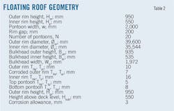
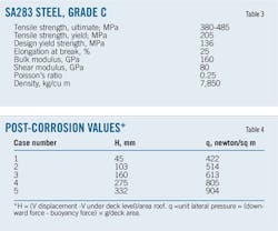
Tables 1-3 describe the studied tank, a vertical cylindrical oil storage tank featuring an external single-deck floating roof and filled with 700-kg/cu m density oil. The tank measures 40 m in diameter and 23 m tall. It was 100% full when tested.
Buoyancy calculations
Buoyancy acting on a deck is related to submergence of the deck above backslope. The height of submergence above backslope is related to the size of the backslope. Floatation depth of the deck is related to the weight of the deck. The ideal condition is for buoyancy forces to equal deck loads or, in terms of floatation, for the submergence above backslope to equal floatation depth of the deck.
If the backslope is too large, the floatation depth of the deck is greater than the submergence above backslope (weight of deck is greater than buoyancy forces) and the deck floats lower in the product than the pontoon, potentially creating a vapor space. If the backslope is too small, the floatation depth of the deck is smaller than the submergence above backslope (weight of deck is less than buoyancy forces). The deck floats higher in the product than the pontoon which can cause rainwater drainage towards the pontoon.
Both Case 1 and Case 2 calculate the flotation level for a corroded roof pontoon: Case 1 under normal operation with no rain on the roof and Case 2 with 250 mm of rain on the roof. Figs. 1 and 2 represent each case respectively.
The maximum submerged height above deck level, Hsub, is 550 mm, so the design is safe even in Case 2's condition.
Rainfall, stress, deflection
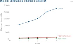
A second study at the same tank compared five different loads applied to the corroded deck plate by using three different analysis methods to study deflection and stresses. The first method applied the equations of stresses and deformations on thin plates derived according to Roark's formulas for stress and strain.4 The second method used numerical nonlinear finite element analysis by applying the load gradually and studying the effect of the large displacement on the material behavior in deformation and stress. The third method was the numerical application of linear finite element analysis with the deck loaded to 100% without consideration of the large deflection effect on the material.
The five different load cases were:
• Case 1: Normal Case, with no rain on the roof.
• Case 2: 50 mm of rain on the roof
• Case 3: 100 mm of rain on the roof.
• Case 4: 200 mm of rain on the roof.
• Case 5: 250 mm of rain on the roof.
When plate deflection becomes larger than one-half plate thickness, as may occur in thin plates, the surface of the middle becomes strained and the stresses in it cannot be ignored because they change the behavior of the plate deflection. This stress is called diaphragm stress. It allows the plate to carry a part of its load as a diaphragm in direct tension. This tension is balanced by radial tension at the edges if the edges are held or by circumferential compression if the edges are not horizontally restrained.
In thin plates, this circumferential compression can lead to buckling. When large deflection occurs, the plate is stiffer than calculated by the ordinary theory of small deflection and the load-stress relations and load-deflection relations become nonlinear. Stresses for a certain load are less than indicated by the ordinary theory of small deflection.
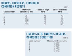
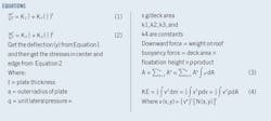
Equations 1-2 give formulas for stress and deflection in circular plates when middle-surface stress is taken into account. These formulas are used to achieve accurate results whenever maximum deflection exceeds half of plate thickness.4 Table 5 summarizes results obtained by applying Roark's formulas for stress and strain.
Non-linear analysis
Solidworks simulation program allowed finite-element analysis (FEA) of the deflection and stresses on the deck plate.5 FEA replaces any complex shape with the summation of a large number of very simple shapes that are then combined to model the original shape. Alternatively we could split the area into a set of triangles (cover the shape with a mesh) and sum the areas of the triangles (Equation 3). Using Equation 4 to integrate over the differential masses yields the kinetic energy of the planar body of "t" thickness.
The linear theory assumes small displacements. It also assumes that the normal-to-contact areas do not change direction during loading, therefore applying the full load in one step. This approach may lead to inaccurate results or convergence difficulties in cases where these assumptions are not valid.
A large displacement solution takes more time and resources than the small displacement solution but gives more accurate results. The large displacement solution is needed when the acquired deformation significantly alters the structure's stiffness (ability of the structure to resist loads). The small displacement solution assumes that the stiffness does not change during loading. The large displacement solution assumes that the stiffness changes during loading so it applies the load in steps and updates the stiffness for each step.
Figs. 3-7 summarize the results obtained by non-linear large displacement analysis.
Linear static analysis
Researchers applied all loads slowly and gradually until they reached their full magnitudes, after which they were held constant. This approach allowed neglect of inertial and damping forces caused by negligible accelerations and velocities.
Time-variant loads that induce considerable inertial or damping forces may warrant dynamic analysis. Dynamic loads change with time and in many cases induce considerable inertial and damping forces that cannot be ignored.
The relationship between loads and induced responses is linear. The linearity assumption in the model can be made to comply with Hooke's law. Stress is directly proportional to strain and the induced displacements are small enough to ignore the change in stiffness caused by loading. Boundary conditions do not vary during load application. Loads must be constant in magnitude, direction, and distribution.
Table 6 describes the linear static analysis.
Punctured pontoons
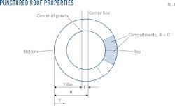
The elastic flexure formula, buoyant forces acting on the effective area of roof and resisting its weight, provides the basis for determining roof buoyancy.6 Fig. 8 shows the punctured roof's properties, including its center of gravity and moment of inertia. The same approach was used in studying the punctured roof's buoyancy under three different conditions:
• Deck plate and one pontoon punctured.
• Deck plate and two pontoons punctured.
• Deck plate and three pontoons punctured.
Calculation of the centroid occurred first, followed by the moment of inertia, the maximum and minimum pressure acting on the floating roof due to the puncture, and the maximum and minimum submerged height of the floating roof due to its weight and tilt.
Fig. 9 shows the wide differences between deck plate deflection using the first two methods (Roark's formulas and nonlinear FEA) and the third method (linear FEA). The numerical linear FEA method is not applicable because it ignores both large displacement's and deformation's effects on strain, deflection, and stresses, and therefore yields much higher results.
Nonlinear FEA is most applicable to designing floating roof decks, simulating loading cases as they happen in reality. Roark's formulas give higher results but can be used for quick deck plate analysis. Linear FEA is not applicable and cannot be used to study floating roof deflection.
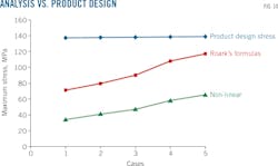
API 650 (Section 5, Table 5-2) puts the product design stress of material A283 Gr.c at 137 MPa. To protect the floating roof from failure, maximum stress must not exceed this value. Fig. 10 shows the design presented in this article as able to carry the five different load cases without failure, even under corroded conditions.
The results show differences between using Roark's formulas of large deflection and nonlinear FEA because the accuracy of the nonlinear method is much higher than Roark's. Both methods, however, are safe.
To increase floating roof-deck safety:
• Use another materiel with a higher product-design stress value, such as A516 Gr.70 or A573 Gr.70.
• Increase deck-plate thickness.
• Apply suitable coatings to prevent corrosion.
The tested floating roof remained floating after the puncture of two adjacent pontoons and deck plate corrosion but sank when the number of punctured pontoons increased to three.
References
1. "API Standard 620, Design & Construction of Large, Welded, Low-Pressure Storage Tanks," American Petroleum Institute, Washington, 1996.
2. Long, B. and Garner, B., "Guide To Storage Tanks & Equipment," Professional Engineering, Bury St. Edmunds, UK, 2004.
3. "API Standard 650, Welded Steel Tanks For Oil Storage," American Petroleum Institute, Strategies For Today's Environmental Partnership, Washington, 1998.
4. Roark, R.J. and Young, W.C., "Roark's Formulas For Stress and Strain, McGraw-Hill, New York, 1989.
5. Planchard, D.C., "Official Guide To Certified Solidworks Associate Exams," CSWA, CSDA, CSWSA-FEA, Solidworks 2012-15, SDC Publications, Mission, Kan., 2014.
6. Hibbeler, R.C., "Mechanics of Materials," Prentice Hall, Boston, 2010.
The authors
Ahmed Saad Noaman ([email protected]) is a mechanical engineer at Petrojet, Cairo. He holds a BS (2008) and MS (2016) in mechanical engineering from Ain Shams University, Cairo.
Mohamed Elsamnody ([email protected]) is a professor at Ain Shams University, from which he holds a PhD.
Ashraf Ghorab ([email protected]) is an assistant professor of engineering at Ain Shams University, from which he holds a PhD (1993).


