Compressor rerating keys North Sea platform enhancement
Roland Pike
Arun Karuppasamy
g3baxi Partnership Ltd.
London
John Gill
g3baxi Partnership Ltd.
Muscat, Oman
A compression train on Hess Denmark's South Arne platform in the Danish North Sea required rerating to meet a planned production profile. The train consisted of motor driven, fixed-speed back-to-back flash-gas compressors.
The project included designing for low-volume flows while accommodating a large variation in gas composition, due to the intermittent operation of a future flare-gas recovery system.
Compressor design for low-molecular-weight gas limits operation at high molecular weight, with the converse also being true. Therefore the objective was to design a compressor that could satisfactorily operate over a range of gas molecular weights.
In addition the redesign needed to accommodate the low-volume flows, which presented obstacles in terms of design (low efficiencies) and selection (limited impeller inventory).
This brownfield modification shows that, with careful consideration and through detailed optimization, it is possible to re-wheel fixed-speed motor driven centrifugal compressors to operate successfully for a wide range of gas molecular weights and operating conditions.
Furthermore these machines can be designed not only for early as-designed performance but also for future in-service operation in which the head capability may be reduced.
The successful design, installation, and operation of this production enhancement project derived from a good understanding of compression systems and brownfield modifications, integrated teamwork, and the free flow of information among the participating disciplines.
Danish North Sea
The South Arne platform in the Danish sector of the North Sea was designed in the mid-1990s during the Cost Reduction Initiative for the New Era (CRINE) and commissioned in 1999. A combination of expansion plans to extend the drilling area as well as other developments meant that a new production profile needed to be accommodated. This involved extensive engineering analysis to determine the process and mechanical bottlenecks.
The original equipment design capacities were suitable to process 70 MMscfd gas and 50,000 bo/d and to accommodate the new production profiles (and gas-lift requirements) the intention being to increase the platform's gas-handling capacity to 85 MMscfd.
Operator Hess Denmark requested g3baxi to evaluate and solve the rerating of the flash-gas compressors, a modification made more difficult by the wide range of anticipated operating conditions.
The g3baxi analysis benchmarked and evaluated the performance of the existing processing train and showed that several of the equipment items required upgrading, including vessel internals, heat exchangers, and gas compression systems and their ancillaries.
As this was a schedule-driven project, with the purchase order for any compressor modifications needing to be placed within 3 months of project kick-off, only replacement of the compressor bundles was considered. This was done to minimize cost, duration, and complexity of the project and to ensure that any modifications were simple enough to enable installation during a shutdown window.
Flash-gas compressors
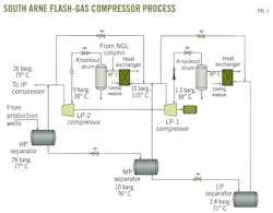
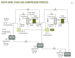
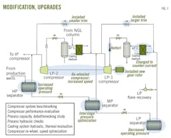
Fig. 1 shows how the flash-gas compressors fit into the process scheme. The scheme is typical for an oil stabilization process: three stages of separation with the associated gas recompressed back to inlet separator's pressure. The original flash-gas compressors were commissioned in 1999 and consist of a fixed-speed electric motor-driven two-section unit, with back-to-back centrifugal compressors (LP-1 and LP-2).
The LP-1 compressor is fed from the low-pressure (LP) separator, the pressure of which is the primary means of controlling the produced oil rvp specification. Feed gas to the LP-2 compressor comes from the LP-1 compressor, the medium pressure (MP) separator, and the gas outlet of the NGL column.
Operation of the flash-gas compressors before the capacity expansion was problematic for several reasons:
• The LP-1 and LP-2 compressors were originally designed for gas molecular weights of 55 kg/kilomole (kg/kmole) and 44 kg/kmole, respectively. The actual molecular weights were much lower than this, however, adversely affecting operations.
Specifically, the LP separator's pressure needed to be raised, which made it harder to meet the stabilized oil rvp specification. Also, the high pressure (HP) separator's pressure needed to be lowered, which decreased the operating pressure of the downstream equipment as well as increasing volumetric flows. The combination of these effects limited the maximum processing capacity of the platform.
• Low flash-gas rates from the MP and LP separators compared with design meant the compressors operated in recycle.
The revised process conditions that resulted from the expansion plans and other development projects meant that the flash-gas compressor rerating needed to accommodate several different factors.
The following design objectives were included:
• Reinstatement of the production separators' operating pressures to their original design values. This was necessary to enable an increase in the gas processing capacity of the downstream compression systems while maintaining the oil export specification.
• Incorporation of future HP and LP flare-gas recovery schemes, which both tie into the LP-1 compression system. Due to the likely intermittent operation of the flare-gas recovery, this led to a wide range of flow rates and gas molecular weights that would be encountered.
The LP-1 stage had a predicted molecular weight variation of 34–44 kg/kmole, whereas the LP-2 stage was more steady at around 34 kg/kmole. The envisioned volumetric gas flows through the LP-1 and LP-2 stages would still be far less than in the original design. Since the compressor casings would be unchanged, engineers expected that the rebundled compressors would continue to operate on recycle following their upgrade.
Benchmarking
Several disciplines were involved in the rerating of the flash-gas compressors, and a key reason for the success of the project was the integrated design approach.
Interfaces between the various disciplines were carefully managed to ensure that responsibilities were clear. The entire design process was not simply a once-through exercise but rather an iterative cycle involving process and machinery disciplines to assist and verify vendor designs.
The initial phase of the work involved benchmarking various simulations of the process against actual plant data, as this allowed models to be more accurate in predicting future flow rates.
The benchmarked simulations were then updated with the latest production profiles (including flare recovery) to identify the equipment bottlenecks and define the brownfield modifications required to accommodate the proposed operational changes.
The heat and material balance information for the flash-gas compressors was passed to the machinery discipline to review the mechanical requirements and develop datasheets that incorporated the anticipated degradation. These datasheets were then passed to the vendor to redesign the bundles.
The updated compressor curves from the vendor were then input to the simulation model for verification. The low-volume flows and wide range of gas molecular weights led to several iterations before a design for the flash-gas compressors was arrived at that was satisfactory from both a process and mechanical points of view.
The main activities for each of the disciplines are given in the following sections.
Process engineering
Acquisition and review of platform operating data for benchmarking purposes took place over two discrete periods of operation, summer and winter operation.
The following plant areas were studied:
• Topsides process. With Aspentech's HYSYS, a rigorous simulation modelled all aspects of the topsides process to determine equipment performance, such as compressor degradation, exchanger performance, and product specifications.
• Platform cooling systems via development of detailed thermal and hydraulic models in order to identify bottlenecks and gauge the effectiveness of the identified upgrades.
Detailed hydraulic models of the process-gas systems were built with PipeFlow Expert software. This was done to improve the accuracy of the pressure-drop modelling in HYSYS and to qualify the existing gas piping for the future production cases. Equivalent pipe lengths were calculated from plant isometrics so that flow-dependent pressure drop formulas could be derived for different sections of the plant.
Development of these models to give an acceptable fit to the benchmark data consequently gave a high level of confidence and meant that the simulations of the future processing requirements were more accurate in predicting any bottlenecks and hence the need for modifications.
Once the benchmarking exercises were satisfactorily completed, the overall HYSYS simulation was updated as follows:
• Inclusion of the new production profile cases. Due to the phased implementation of the various upgrades, there were 2 distinct design years that needed to be modelled.
• Addition of HP and LP flare recovery systems, upstream of LP-1. It was envisioned that these would operate intermittently, which meant the LP-1 gas molecular weights would vary 34-44 kg/kmole.
• Modelling of the compressor suction throttling valves, with the ability to calculate pressure drops. This allowed the user to ensure that the valves' percentage openings were within their normal operating range.
• To accommodate future design cases, revised compressor head and efficiency curves were input. As stated earlier, this was an iterative procedure, with the design improving each time until a satisfactory solution was achieved. An allowance was made for degradation in the later design years, and it was assumed that full degradation would occur within 3 years of installation.
• Automatic calculation of the LP-1 and LP-2 stage recycle points based on the gas molecular weight and surge margins recommended by the machinery discipline.
• Inclusion of formulas to calculate the gas-side pressure drops based on flow rate.
Several simulations were run for the 2 design years both with and without flare-gas recovery. The operating conditions around the flash-gas compressors were adjusted to ensure that the oil product rvp specification was met and to return the LP-2 discharge pressure to the original design value.
This exercise also involved optimizing the interstage pressure (that is, MP separator pressure).
Once the revised HYSYS simulations were completed, the results were input into the thermal and hydraulic cooling system model to determine whether the anticipated cooling loads could be met and, if not, what modifications would be required.
The flash-gas compressor suction coolers were both Alfa Laval plate-frame exchangers.
Results from the revised simulations identified the following process equipment bottlenecks and subsequent modifications around the flash-gas compression equipment:
• The new compressor bundles resulted in modified recycle points for each compressor stage, with the LP-1 recycle valve requiring a smaller trim and the LP-2 required a larger one.
• The reduction in the volume flow through the LP-1 compressor was such that the differential pressure across the existing venturi flowmeter approached the low range of the pressure transmitter. Consequently, to increase the pressure-drop, we replaced this unit with a new instrument with a reduced throat diameter.
• To accommodate the higher discharge temperatures during start-up, we changed the LP-1 suction cooler from cocurrent to counter-current operation and added plates.
• The flash-gas compressor lube oil cooler was predicted to be undersized and was replaced.
Compressor re-wheel
The flash-gas compressor re-wheel was carried out with the following objectives:
• To optimize the impeller selection to accommodate a wide range of molecular-weight variation and at the same time reduce recycle rates to keep the power requirements within the driver's power limits with enough margin for future in-service performance.
• To increase the head capability of the compressors to restore the production separator's operating pressures back to their original design values.
Meeting these re-wheel design objectives was difficult due to the operational constraints and design limits discussed in the following sections.
High molecular weight
It was difficult to restore the original design pressures for the HP and LP separators due to the high molecular weight gas assumed in the original design (about 55 and 44 kg/kmole, respectively, for the LP-1 and LP-2 stages) This meant that the compressor needed to generate relatively less head to deliver the required pressure ratio.
In contrast, the lower molecular weights for the future production scenarios meant the compressor had to develop higher head to deliver a similar pressure ratio.
Design limits
The requirement to restore the original pressure ratio was further complicated by the casing design limits, as there was no room for additional impellers and there was also an absolute limit to the impeller diameter increase that could be accommodated to provide the additional head requirement.
The other method to deliver the required additional head was to increase the compressor speed by installing a new gear rotor. This would only be possible if the center line of the shafts remained unchanged, meaning that the existing base plates could still be used.
Performance shift
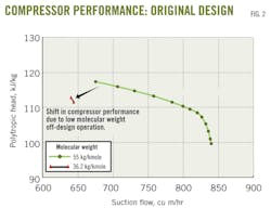
The performance of centrifugal compressors is a function of operating conditions (suction pressure, temperature, and molecular weight) and is particularly sensitive to the latter. A small change in the molecular weight can result in a large shift in performance due to a change in compressibility per stage affecting the volumetric flow, resulting in early choke or surge.
Fig. 2 shows the sensitivity in compressor performance for the original design with a low molecular weight off-design operation.
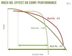
Mach number also affects compressor performance. As Mach number increases, the operating range decreases (Fig. 3). If the compressor is designed according to the API Standard 617 (seventh edition) recommendation for the lowest molecular weight gas composition and the highest head and flow requirement, then the operating range for high molecular weight off-design operations shrinks, similar to that shown in Fig. 2.
Low flow coefficient
The low flow and high head requirement for the LP-2 stage complicated impeller selection for the following reasons:
• Low efficiencies associated with low-flow-coefficient design with narrow impeller passages resulted in a low driver power margin.
• Limited impeller availability for low flow-high head designs associated with manufacturing difficulties.
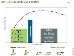
The logical approach to selecting a relatively efficient impeller was also deemed unsuitable due to the high recycles rates associated with a high flow design. Hence the plan was to optimize the impeller selection so that the efficiency was high enough for good driver power margin and at the same time the recycle rates for off-design operations were acceptably low (Fig. 4).
Design
The requirements and design problems discussed thus far required an integrated project approach for a successful compressor design selection within the tight project schedule.
Several design iterations were required to understand the design limits (maximum impeller diameter, maximum compressor speed increase possible), process limits (separator pressures, flows, and molecular weight change), and operational limits before a final design solution was arrived at.
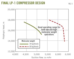
In order to get a good compressor operating range for all off-design operations, the design approach adopted was to select a mid-molecular weight so that it resulted in a good operating range for both high and low molecular weight operations. With project's schedule in mind, two design options were proposed and evaluated simultaneously:
• No change in the design speed; only the impeller diameter would be increased to achieve the required duties.
• Increase in the design speed by increasing the gear ratio without affecting the shaft centerline distance and the required critical speed separation margins.
The second option design was recommended for the rerating because it exhibited a good driver power margin and required a low starting current and torque (due to the low-volume flow design).
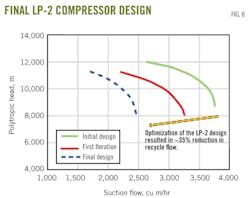
Figs. 5 and 6 show the final LP-1 and LP-2 designs and the optimization carried out to arrive at the final designs.
Modifications; commissioning
Fig. 7 shows a summary of all modifications related to the upgrade of the flash-gas compression equipment.
The modifications to the flash-gas processing equipment were carried out in September 2011, and engineers from the design team joined the commissioning team offshore.
Commissioning of the new compressor bundles proceeded relatively smoothly and encountered no problems in any of the mechanical tests or in setting up the anti-surge control parameters. There were also no complications in the commissioning of any of the ancillary items.
Independent performance mapping carried out in real time by engineers from the design team found both machines met the design head requirements.
The LP-1 compressor initially operated close to choke conditions because of the high head capability of the new bundle. This was expected because the machine initially had high head-capability to allow for future in-service fouling and the gas molecular weight was initially high because the flare-gas recovery system was not in service.
The LP-2 compressor was found to operate with a flow rate somewhat higher than design. Measurements made during commissioning revealed the compressor was capable of meeting the design objectives, but at higher compression powers. This increase in power caused a trip on start-up during the commissioning tests. The design team was aware of this as a potential issue and had already considered a technical solution, which was to reduce the discharge pressure during start-up only.
These findings were conveyed to Hess Denmark with the benefit of allowing it to consider the solutions and make adjustments to the flash-gas compressor systems using the commissioning personnel aboard. This approach minimized the risk to production associated with the commissioning activities.
Since commissioning, the compressors have operated successfully with high availability and few operational issues. The new compressor bundles have allowed the production separator operating pressures to be adjusted to meet the design objectives.
The flare-gas recovery system was commissioned in September 2012, and the LP-1 compressor provides the required head to accommodate low molecular weight operation when the flare-gas recovery system is in operation.
The machinery performance is suitable for future operation if the head capability is reduced due to in-service fouling.
Acknowledgements
For their assistance, the authors would like to acknowledge from Hess South Arne's Mark Roberts, project manager, and Kath Mansfield, engineering lead.
The authors
Roland Pike ([email protected]) is a senior consultant at g3baxi partnership based in the UK. He has more than 20 years' experience in the industry, with the main areas including project management, production optimization, field development planning, and feasibility-conceptual studies. Pike holds a bachelors in chemical and process engineering from Surrey University, UK.
Arun Karuppasamy ([email protected]) is a rotating machinery consultant at g3baxi partnership's UK office. He has experience in the design and development of turbomachinery specializing in compressors and gas turbines for upstream oil and gas. He holds a masters degree in aeronautical engineering from the Indian Institute of Technology, Kanpur.
John Gill ([email protected]) is a process engineering consultant at g3baxi partnership, currently working on projects in the Middle East and Africa from the company's subsidiary office in Oman. His main areas of experience are conceptual engineering and frontend engineering and design studies for upstream oil and gas. Gill holds a masters (2003) in chemical and process engineering from Sheffield University, UK.
