Common errors can cause mol-sieve desiccant deterioration
This article describes the Yanbu gas plant’s dehydration facility and the plant’s encounter with solid-desiccant deterioration in October 2006.
Identified are the main contributing factors that have resulted in acceleration of bed decomposition. The article also provides a list of the most common operational mistakes that eventually wind up as adopted practices for operating dehydration units.
Finally it illustrates the proper configuration for loading different layers in dehydrator beds.
Bed deterioration
Molecular sieve dehydration removes entrained water from treated propane and butane to produce on-specification LPG with water levels of less than 10 ppm.
The Yanbu gas plant consists of four dehydration units: Two serve the stream coming off the depropanizer columns, while the other two units process butane.
A single dehydration facility consists of two identical beds that work interchangeably; during normal operation one of the dehydrators is put online to dry the wet hydrocarbon steam, while the other bed is being regenerated.
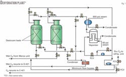
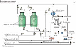
The dryers run on automatic cycles controlled by a preset water load that is normally obtained from annual breakthrough testing. Fig. 1 shows a simplified diagram of the dehydration unit.
A water-breakthrough test (dehydrator performance) on the butane dehydration train in 2006 revealed a total adsorptive capacity of the desiccant bed to be about 9.5 (lb H2O/100 lb desiccant), which corresponds to nearly 44% activity. Furthermore, the maximum ∆P across the bed was recorded at 9 psi, which is fairly high compared to design values of 6 psi. (Differential pressures normally range 2-6 psi but could reach as high as 12 psi without affecting the bed integrity.)
Seeing the reported ∆P was unusually high, plant operations decided to carry out scheduled test and inspection 3 months ahead of plan. The initial inspection of the dehydrator vessels revealed excessive decomposition of the old desiccant. About 60% of the bed was transformed to powder-like particles as opposed to a typical transformation rate of 30%, at similar service periods and operating conditions.
The plant’s process engineer conducted a thorough study subsequently to determine the cause of high-powder formation in the system. A detailed review of historic data revealed that these particular beds contained desiccant batches from two different vendors, which were loaded during the previous test and inspection.
The fact of having loaded the dehydrator with two different brands of molecular sieves instigated the process of ion leaching during regeneration between the different binder additives which eventually weakened the desiccant and accelerated its deterioration.
Corrective actions
In light of YGP’s encounter with desiccant failure, the plant initiated several preventive measures to eliminate any possibility of recurrence.
- Old desiccant batches can only be reused in an emergency situation after being analyzed for capacity and crush strength.
- Mixing of desiccant from different vendors is no longer permitted.
- Water breakthrough tests shall be conducted annually to monitor performance of desiccant beds.
Common errors
There are many operational factors that could accelerate desiccant aging; some have been adopted industry wide with little regard and understanding of long-term consequences.
- Introducing inlet feed velocities lower than 3 fpm or higher than 5 fpm.
- Operating the dehydrator units at high differential pressures.
- In the process of topping off desiccant beds, placing the old batch at the bottom of the bed.
- Mixing desiccant obtained from different manufacturers in the same dehydrator.
- Applying inaccurate loading configuration procedures.
Proper loading
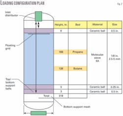
Each manufacturer might have its own plan of loading configuration for different layers within the bed. The following method, however, reflects the general setup based on engineering standards and international codes.
- A 2-3 in. layer of 0.5-in. ceramic balls is placed at the bottom to provide required bed support and improve flow distribution during adsorption.
- An additional 2-3 in. of 0.25-in. layer is placed atop the previous one to prevent adsorbent nesting in the free space between support balls.
- A 6-in. layer of 0.5-in. ceramic balls is inserted at the top of adsorbent bed to prevent bed movement and improve flow distribution during regeneration.
Fig. 2 shows correct loading configuration.
The author
Ahmed S. Ghazal joined Saudi Aramco in 2002 and has been working at the Yanbu gas plant since. For the past 6 years he has assumed responsibilities of process engineer at several operating areas, mainly the utilities unit, product handling unit, and the fractionation and treating facility, where he now serves as lead engineer. Ghazal holds a BS (2001) in chemical engineering from King Fahd University of Petroleum and Minerals.


