LNG Recondensing-1: In-tank recondensing improves FSRU transfer efficiency
Maksym Kulitsa
FSRU consultant
Odessa, Ukraine
David A. Wood
DWA Energy Ltd.
Lincoln, UK
Opportunities remain to improve floating storage and regasification unit (FSRU) equipment designs despite the introduction of highly efficient dual-fuel diesel electric (DFDE) FSRU. A new opportunity to improve FSRU efficiency uses natural recondensing inside LNG cargo tanks during ship-to-ship (STS) cargo transfer.
The proposed concepts and design modifications are effective irrespective of whether traditional recondensing systems are installed or not and are not related to such systems.1 The modifications serve instead as additional temporary boil-off gas (BOG) handling capacity for no incremental operating costs at times when FSRU most need it. With no additional power input required the solution treats some BOG, reducing tank pressure during STS transfers. The same method can be used during regasification for limited periods of time to handle certain tank pressure excesses.
LNG conditions
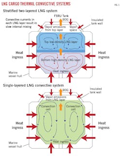
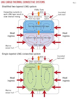
LNG in tanks is maintained in a homogenous condition and constantly mixed through its entire volume by thermally induced convection currents. Where stratified layers of LNG exist the same process is at work, but within the mass of each level (Fig. 1).2
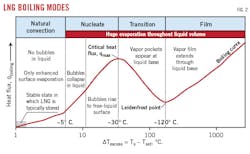
LNG in tanks typically exists at a natural convection boiling state (i.e., evaporation occurs from the surface, and, although the liquid is at its boiling point, no gas bubbles appear within it) rather than at a nucleate boiling state in which free bubbles exist. (Fig. 2).3 This has high relevance to LNG in storage because the natural convection boiling state and convection itself suggest that the lower LNG layer can gain some heat without nucleate boiling. Consequently, as LNG gains heat, it first must travel to the liquid surface in the tank and only at that point does it yield a flash of vapor.
Taking into account the liquid column height and the hydrostatic pressure head of the overlying LNG mass, the LNG pressure grows as its depth below the LNG surface increases. Therefore, its boiling point at the bottom of a tank is at a different temperature (slightly warmer) than the LNG at the surface. The expected temperature profile of LNG in a storage tank is warmer at the bottom of the liquid column, becoming progressively colder moving in an upwards direction through the liquid. It is more complex than this, however, because convective currents are created (by warmer LNG rising) that effectively keep the LNG bulk in a homogenous state.
In practice, the temperature difference between the top and bottom of the liquid column (or within a specific stratified layer), measured by vertical temperature sensors, is not more than 0.1° C., meaning the LNG has almost the same saturated vapor pressure (SVP) throughout its vertical height. Thus, the LNG is saturated (i.e., at its boiling point) only at and near its surface. The remaining liquid below the surface is sub-cooled (compressed by the overlying liquid), and becomes progressively more sub-cooled as its depth from the surface increases.
Typically, a full FSRU tank, with a liquid column height of 26 m, exerts an additional hydrostatic pressure of 100-120 mbar on the LNG at the bottom of the tank. Consequently, the LNG at the bottom of the tank requires heating by 1.0-1.2° C. to reach saturation point.
In-tank recondensing
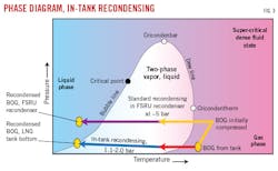
In-tank recondensing exploits the sub-cooled nature of LNG near the tank bottom. It involves transporting vapor from the top of the tank and injecting it into the mass of sub-cooled LNG near the tank bottom, where it recondenses. In the process of vapor condensing, the sub-cooled LNG near the tank bottom accumulates the latent heat of vapor condensation. This portion of LNG warms up due to heat accumulation and the condensed BOG adds mass to the liquid, the basic principle of standard LNG recondensers fitted on many FSRU and shore-based regasification terminals. Fig. 3 shows a phase diagram for in-tank recondensing compared to recondensing produced in a conventional FSRU recondenser.
The local LNG mass becomes heated (up to its saturated state), and, as its density decreases, buoyancy causes it to rise in the tank. During upwelling, this LNG either fully dissipates or partially mixes with other colder LNG through which it passes by convection within the whole tank or a single stratified layer (Fig. 1).
As the condensed LNG disperses into the LNG bulk, its temperature and SVP slowly increase. Despite the rising SVP of the bulk LNG, a reduction in tank pressure and SVP near the LNG surface is achieved by removing some vapor from the top of the tank, with the LNG in the tank becoming warmer. Condensing cryogenic natural gas vapor results in a 250× volume decrease at tank conditions.
This method can achieve tank-pressure reduction only to the level of the prevailing LNG-bulk SVP pressure and equilibrates to SVP changes. When applied during STS transfers, the tank pressure equilibrates to the prevailing LNG SVP, and increases as the LNG SVP increases during bulk LNG warming.
When this technique is not applied during STS transfers, tank vapor is compressed and tank pressure generally rises to much higher levels than the SVP of the LNG bulk, which occurs in standard LNG recondensing if the condensed LNG is recirculated to the cargo tanks.1 Condensing tank vapor via this in-tank circulation method theoretically stops when local tank-bottom LNG warms to its SVP and is no longer sub-cooled. This is unlikely to occur during STS transfers, however, due to the continuous introduction of fresh, cold LNG supply and the increasing liquid mass that occurs during such operations. The process therefore can run safely until the tank pressure slowly approaches its upper operating pressure.
Even when LNG at the tank bottom near the injection point becomes momentarily saturated, and some vapor remains uncondensed, the bubbles will be forced upwards creating significant turbulence. That turbulence will aid the dispersion of the uncondensed BOG into the LNG bulk and, eventually, most if not all the recirculated BOG will be condensed in the overlaying mass of LNG, which is colder than the locally-saturated LNG below. Eventually some vapor bubbles may emerge from the LNG surface, but only if the LNG layer height is very low, like when an STS transfer begins into a small heel cargo in an FSRU tank.
Vapor that manages to pass through the LNG and return to the tank’s vapor space will be at, or close to, the temperature of the LNG bulk. It will still have been cooled and shrunk, however, in comparison with the vapor near the top of the space from which it originated.
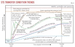
As the tank gradually fills during STS, condensation of the recirculated BOG will become more effective, with all recirculated BOG likely to be condensed by the latter stages of an STS transfer. Fig. 4 shows typical expected tank pressure and temperature trends during STS transfer, with and without in-tank recondensing.
Depending on liquid height available in a tank or LNG layer, the condensing capacity of this technique will vary from extremely low, for a nearly empty tank, to maximum condensation at full-tank conditions. A thick vertical LNG column also enhances the dissipation of the rising, warm LNG into the bulk of the LNG layer, avoiding the vapor flash generated when a plume of warm LNG emerges at the liquid surface.
The technique presented is limited, therefore, by tank pressure equilibrating to LNG-bulk SVP. The SVP of the LNG generally rises during such operations and tank pressure parallels that rise. Once tank pressure, aligned with SVP, approaches the safe upper operating limit of a tank, application of this technique should cease.1
When tank conditions lead to the vapor-space at the top of the tank being compressed, typically during STS transfers, tank pressure may rise to the safe upper operating-pressure limit, while the SVP of the LNG bulk remains at a much lower value. Such conditions are inherent to all mid-to-high-rate STS transfers in which the vapor space at the top of the tank is compressed by the incoming liquid volume and insufficient volumes of vapor are evacuated from the tank to relieve that compression. The entire LNG column becomes progressively more sub-cooled (compressed), except for a thin surface layer, the Hashemi-Wesson layer.2
Applying the in-tank recondensing concept during STS transfer, therefore, leads to warmer LNG in the tank (which is not a problem for FSRU) but a lower tank pressure. Without applying the in-tank recondensing concept, the LNG in the tank remains colder but the tank pressure rises significantly faster, and eventually needs to be controlled by running the gas combustion unit (GCU) or steam dump (Fig. 4).
Consider the tank condition in which LNG SVP is at 1,133 mbara (about 120 mbarg tank pressure), but prevailing tank pressure due to packing is 1,213 mbara (200 mbarg). This excess tank pressure of 80 mbar above SVP causes compression of the liquid by the vapor phase. The excess pressure over SVP of 80 mbarg is equivalent to a roughly 0.8° C. liquid temperature increase of the LNG required for it to become saturated again in the portion of LNG immediately below the liquid surface.
If the tank is 50% full, the impact of hydrostatic compression on the LNG in the bottom of the tank due to the height of the LNG column alone is 50-60 mbar. The LNG at the tank bottom is therefore in a sub-cooled state of 80 + ~55 = ~135 mbar, equivalent to about a 1.35° C. temperature rise for the bottom LNG to reach saturation state. This LNG can absorb significant recondensation heat from large vapor mass.
There is a double benefit that results from applying the concept:
• At higher LNG tank levels it results in full condensation of the vapor transported to tank bottom.
• At low LNG tank levels it cools and shrinks injected vapor, with only a little of the vapor being condensed.
Benefits, therefore, result from applying the concept to any tank-fill conditions, but the magnitude of those benefits varies depending on specific tank-fill conditions.
The technique was proven in observed cases during cooldown of a pair of 800-m shore-side liquid transfer lines. All BOG generated was sent directly to the FSRU tank bottoms, two tanks filled to less than 10% capacity (OGJ, Nov. 6, 2017, pp. 56-60; OGJ Dec. 4, 2017, pp. 65-70). Within 1 hr, the induced FSRU tank pressure (where no vapor return was permitted) increased only 20-30 mbarg.
If the traditional practice had been applied—directing BOG directly into the FSRU tanks’ vapor space—much higher tank pressure increases would have occurred. Such a low tank-pressure increase can only be explained by recondensation of some of the generated BOG and cooling of the vapor not condensed, the two-fold benefit.
BOG delivery
The most suitable scenario for applying the concept is during STS transfers. When LNG passes through an in-tank vertical pipe it accelerates due to gravity. This liquid velocity increase and mass continuity creates a Venturi effect like that exploited by ejector and jet pumps that use pressurized flowing liquids to entrain, mix, and pump other fluids by creating a vacuum or pressure reduction.4
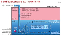
The LNG loading pipe can be designed to exploit the Venturi effect, entraining BOG from the tank’s vapor space and delivering it to the LNG at the bottom of the tank. The fundamental design requirements of LNG loading pipes mean that only minor throttling to increase the velocity of the flowing LNG is feasible. Excessive velocity would generate high back pressure in the common liquid transfer header. Increasing liquid velocity near the tank ceiling is achieved by narrowing the aperature of the loading pipe at this point. Excessive throttling, however, is to be avoided as it would lead to an unacceptable pressure rise.
Consequently, the Venturi effect has to be achieved mainly by gravitational acceleration of liquid flowing down into the tank rather than by pressurizing the flowing liquid (as is the case with traditional Venturi-based devices). Its suction capacity would therefore be less than that of eductor pumps, but sufficient for entraining some BOG from the tank vapor space during tank loading.5 Also, excessive suction eventually forces additional evaporation, so a relatively low-capacity system is optimal.
This in-tank BOG transport-delivery concept consumes no additional energy as it involves no additional pumps, compressors, etc. Using the Venturi effect initiated by falling LNG liquid, some of the tank vapor is entrained through special nozzles in a specifically designed or modified loading pipe section traversing the tank’s vapor space.
Entrained vapor is sucked into the flow stream of LNG loaded into the tank and transported to the tank bottom, where it condenses or cools (Fig. 5). A minimum liquid flow rate through the loading pipe is essential to create necessary suction pressure. During STS transfers liquid flow rates into each tank are high enough for the concept to work. Also, STS loadings typically increase tank pressure, requiring more BOG handling capacity. The concept provides a dynamically self-balanced outcome. Its condensing capacity increases as the tank progressively fills, while, at the same time, the tank’s vapor space is compressed to a higher pressure, increasing LNG sub-cooling, which in turn leads to higher BOG suction into the loading pipe. Higher STS transfer rates are more efficient, thus the system encourages higher transfer rates, unlike systems without in-tank recondensing.
Part 2 of this article will propose and explain a conceptual design for a modified LNG loading line (MAXO-pipe) into an FSRU tank that exploits the principles of in-tank recondensing.
References
1. Kulitsa, M., and Wood, D.A., “Exploitation of FSRU Recondenser During Regasification Interruptions or low Gas Sendout Rates to Minimize LNG Cargo Losses,” LNG World Shipping, White Paper, 2017.
2. Society of International Gas Tanker Terminal Operators (SIGTTO), “Guidance for the Prevention of Rollover in LNG Ships,” 1st Edition, London, 2012.
3. Cengel, Y. and Ghajar, A., “Heat and Mass Transfer: Fundamentals and Applications,” 5th Edition, WCB/McGraw-Hill, New York, 2014. pp. 598-648.
4. Power, R. B., “Steam Jet Ejectors for The Process Industries,” 1st Edition, McGraw-Hill, New York, 1993.
5. Benjamin, T., “Eductor pumps: the calculations,” World Pumps, Vol. 2001, No. 2, February 2001, pp. 34-38.
The authors
Maksym Kulitsa ([email protected]) is an FSRU onboard operator with more than 8 years’ experience on different regas systems at different FSRU terminals. Kulitsa has taken a personal interest in optimizing FSRU-related operations and improving efficiency.
David A. Wood ([email protected]) is the principal consultant of DWA Energy Ltd., UK. He has more than 35 years of international oil and gas experience spanning project operations, technical evaluations, research, contract negotiations and senior corporate management. He served as the editor-in-chief of the Journal of Natural Gas Science and Engineering from 2013 to 2016.
