Thermodynamic properties are important in predicting pipeline operations accurately
An algorithm has been proposed to estimate pressure drops and flow conditions along single-phase gas and low liquid-content, two-phase-flow natural gas pipelines.
The Masjed-I-Soleiman (MIS) to Mahshahr gas pipeline in southwest Iran was used to demonstrate the impact of different design variables on liquid formation in the line and on line pressure drop.
Liquid formation
Nearly all natural gas contains a heavy fraction that is reported in the gas analysis as a C6+ or C7+ fraction. The fraction normally contains a mixture of compounds and frequently is the determining factor in fixing the dewpoint of the gas.
Liquid formation in a natural gas pipeline changes the line pressure drop and flow characteristics. A seemingly inconsequential amount of liquid can cause significant changes in line pressure drop and capacity.
The liquid will accumulate in low spots and immediately before pipeline elevation increases, causing additional problems in line operation.
In extreme cases, lines designed for gas flow may be incapable of operating when liquid forms and the line must transport a two-phase mixture.
An arbitrary normal paraffin (such as n-C7 or n-C8) will produce calculation results of sufficient accuracy for many tasks in gas processing. More-detailed information on the fraction is required, however, for predicting gas dewpoints and trace-liquid formation.
Incorporating a C6+ or C7+ fraction in an equation-of-state calculation requires that information be available about the density, normal boiling point, critical temperature, critical pressure, and acentric factor for the component.
Both temperature and pressure vary along the length of the line in most natural gas pipelines. Liquid may form at any point. In addition, retrograde condensation may also occur, even at pressures of 1,000 psia or less.1 Consideration of all these possibilities requires that an extensive algorithm be developed properly to organize the calculations and make certain they are completed in the correct sequence.
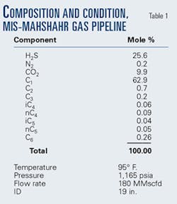
Table 1 shows the gas analysis used as the basis for design of the MIS-Mahshahr pipeline. There is a small amount of C6 (hexane) in the analysis for which the specific gravity is 0.7. This is larger than the reported gravity of hexane (0.6) and even larger than the reported specific gravity of n-heptane (0.69).2
Calculations using the heaviest component as hexane (C6) show the stream to be well above its dewpoint at all points on the pipeline. Using the heaviest component as heptane (C7) shows the gas above its dewpoint at pipeline inlet, but liquid forms down the line.
Using the heaviest component as octane (C8) shows liquid present at the inlet and throughout the length of the line.
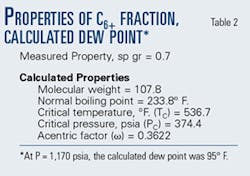
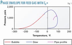
The decision was made to develop the properties of the "C6" fraction, treating it as the mixture of components it truly was. The parameters for the C6+ fraction were calculated using the procedures recommended by Maddox and Lilly.3 As recommended, the pseudo critical temperature of the C6+ component was adjusted to 537° F., which value gave a calculated dewpoint for the gas of 1,170 psia at pipeline inlet. Table 2 shows the properties of the C6+ fraction that match the gas dewpoint.
Fig. 1 shows the two-phase, pressure-temperature envelope when describing the C6+ fraction as a C6+ fraction with the parameters shown in Table 2. With C6+ as a pseudo component fraction with the properties shown in Table 1, the gas is at its dewpoint leaving the separators. There is no liquid at the inlet, but liquid is formed further along the line.
Characterization of the C6+ fraction will, under normal circumstances, have negligible impact on the equation-of-state-calculated bubble point of a natural gas mixture.
Several correlations and calculation procedures are available for estimating pressure drop and flow characteristics for a gas pipeline in single-phase gas or vapor-liquid, two-phase flow. Many of these techniques are intended for application to lines of some length, and all assume that the line does have either one phase or two phases flowing through the entire length of the line.
Akashah4 and Akashah, Erbar, and Maddox5 demonstrated the advantages of incorporating an equation of state in two-phase flow pipeline calculations. One of the great advantages of incorporating the equation of state is that it allows for a priori estimation of liquid formation at any point in a gas pipeline or gas and liquid pipeline.
Proposed algorithm, methods
A calculation algorithm similar to that of Akashah4 was developed to estimate pressure drop in single-phase gas or two-phase natural gas pipelines. The methods selected for individual calculations were arbitrary by the authors. Many other equally suitable procedures can be found in the literature. The following is the method used:
- The Panhandle A, Panhandle B, and AGA procedures were used to estimate pressure drop-flow rate for lines containing no liquid.6 For an unknown flow situation, the first assumption always is that no liquid is present.
- The AGA,7 8 Beggs and Brill,9 and Lockhart and Martenilli10 methods were used for two-phase flow pressure-drop calculations.
- In all cases, the required physical and thermodynamic properties and vapor-liquid equilibrium constants are obtained from the Moshfeghian and Maddox11 computer programs based on the Soave12 version of the Redlich-Kwong13 equation of state. In addition, viscosities were calculated by the method of Thodos, et al., as discussed in Reid et al.14Surface tensions were estimated by the method outlined in the GPSA Engineering Data Book.2 Liquid densities were calculated by the Costald method presented by Hankinson and Thomson.15Maddox and Lilly3 discuss at length the necessity for properly and accurately characterizing the heavy component in natural gas streams if one expects to make an accurate assessment of their vapor-liquid equilibrium behavior. Maddox and Lilly present detailed calculations for obtaining properties of pseudo component fractions and include one example almost identical to the one needed here.
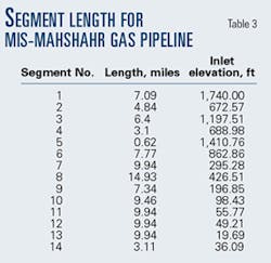
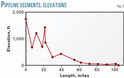
- Divide the pipeline into segments. These segments may be of different lengths but should be chosen carefully to provide the information sought through the calculations to be made. A high point or a low point in the line will typically be a logical beginning or end point of a line section for calculation purposes.The more segments, the longer the calculation time. Time, however, is a relatively small investment compared to the importance of adequate representation of the line profile.The 104.4-mile length of the MIS-Mahshahr pipeline was divided into 14 segments (Fig. 2).Generally, segments terminate at a line high point or low point, with a secondary proviso that maximum segment lengh should not be more than about 10% of total line length.Table 2 shows the length of each segment. The line ID is 19 in.
- Assume a discharge pressure for the pipeline and make a first estimate of the discharge pressure of each segment by use of linear interpolation or any suitable method along the length of the line. Note that the outlet pressure of the first segment automatically becomes the inlet pressure to the second segment.
- For the first iteration calculation, assume the flow of gas (or gas and liquid) in the segment to be isothermal.
- Calculate the average temperature (Tavg. = [TOUT + TIN]/2) and pressure (Pavg. = [PIN + Assumed POUT]/2) for the first segment in the line. For the first iteration, the inlet and outlet temperatures for the segment will be the same because isothermal flow is assumed.8. Using the equation of state, perform a flash calculation at Tavg. and Pavg. using the full stream (combined gas and liquid) composition to determine wheth er liquid is formed in the segment.If no liquid is formed, the pressure drop in the segment is calculated with a dry-gas correlation, such as the Panhandle B or AGA equation.6 If the calculations show that liquid is formed in the segment, the liquid composition (xi), vapor composition (yi), and fraction of feed condensed (L/F) are calculated, and thepressure drop in the segment is calculated with a two-phase flow pressure-drop-correlation equation.
- Compare the calculated pressure at the end of the segment with the pressure that was assumed in Step 5 above. If the difference in these pressures is sufficiently small, proceed to Step 10.If the difference between the assumed and calculated pressures at the discharge end of the segment is too large, replace the assumed outlet pressure with the calculated value of outlet pressure and repeat Steps 8 and 9 as many times as necessary to calculate a suitable segment outlet pressure.
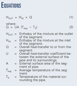
- Calculate the enthalpy at the end of the segment by writing an energy balance around the segment, using Equation 1 (Equation box).
- Perform a flash calculation for the mixture at the (assumed) temperature and (calculated) pressure conditions at the outlet end of the segment to determine the ratio of vapor and liquid required to sum to the outlet enthalpy calculated in Step 10.The liquid and vapor hold-ups in the segment are assumed to be constant with time. Therefore, the total mass flowing through all segments of the line is the same and is constant with time. (Note that the relative amount of liquid and vapor can change from segment to segment, but the total mass flow must be constant and the same at every point in the line.)
- If the temperature calculated in Step 10 is the same as that assumed in Step 7, the calculations proceed to the next segment of the line. If the temperature is different from that assumed in Step 7, calculations revert to Step 7 using the newly calculated value for the segment discharge temperature.
When conditions at the outlet of the last segment of the line have been calculated to a satisfactorily small difference, calculations for flow conditions in the pipeline are complete.
This stepwise sequence of calculations has been used to predict behavior in a number of real and synthesized systems. It has proven to be robust and rugged and has not yet failed to come to a converged solution for each segment of every line it has been tried on.
MIS-Mahshahr pipeline
The authors were asked to determine why the MIS-Mahshahr pipeline was bearing liquid. The pipeline transports natural gas from MIS to the Razi petrochemical complex some 100 miles away.
After beginning work, using the equation of state and the gas analysis provided, they determined the need for the calculation algorithm. Work on the two proceeded in parallel.
Natural gas from each well in the MIS gas field is expanded through a valve or choke into a heater to prevent hydrate formation. The gas from all wells is commingled in the gathering system and collected at a central point where liquid is separated. After the liquid is separated, the gas flows through a solid desiccant dehydrator and then to the pipeline.
The MIS-Mahshahr pipeline was intended to operate as a single-phase gas line and was designed and built on that basis. When the pipeline was commissioned, however, pressure drop through the line was much greater than design.
At design outlet pressure, gas flow through the line was considerably less than the design basis. At design flow rate, the line discharge pressure was much less than design. Operation of the line clearly showed liquid to be present, even though calculations during design of the line indicated there would be no liquid and the line would be handling dry gas.
The design capacity of the line was 220 MMscfd. During summer operating conditions, the maximum gas flow rate was no more than 180 MMscfd. During winter, the maximum capacity was about 165 MMscfd. Also during winter conditions, pigging of the line was required about every other week.
In order to study the impact of design variables and the sensitivity of calculations, computer calculations for the line were carried out with the Ez-Thermo software developed by Moshfeghian and Maddox11 and appropriately modified to carry out the single and two-phase flow calculations.
Overall coefficient
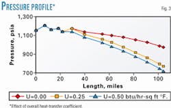
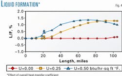
The overall heat-transfer coefficient is used in Equation 2 for energy balance calculations. For the comparison, the overall heat-transfer coefficient was varied from 0 (not right) to 0.50 (probably high) btu/hr-sq ft-°F.
Fig. 3 shows the effect of the overall heat-transfer coefficient on the pipeline temperature profile, and Fig. 4 shows the effect on liquid formation.
Pressure-drop calculation
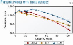
Most methods for two-phase pressure drop calculation contain some empiricism and generate some error. Three different methods were used to calculate the pipeline: AGA, Beggs-Brill, and Lockhart-Martenelli.
Fig. 5 compares results for calculated pressure drop through the line for the three methods. There is considerable difference in the pressure drops among the three calculation methods.
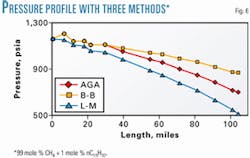
Fig. 6 compares pressure-drop calculations for a man-devised system consisting of 99 mole % methane and 1 mole % normal pentadecane (n-C15) in which the liquid fraction present is essentially constant for all temperatures, pressures, and pressure drops.
The Beggs and Brill procedure predicts the lowest pressure drop. The Lockhart-Martinelli is next, and the AGA predicts the highest pressure drop. Apparently, the pressure drop calculated is a function of the particular method.
Results
This work clearly shows the importance of proper pseudo-component characterization and accurate phase-equilibrium calculations in practical design of gas pipelines.
Incorrect characterization of the C6+ fraction can lead to completely erroneous conclusions about the presence or absence of liquid, even to indicating a line would be handling dry gas when in reality the line would be in two-phase (gas-liquid) flow.
Accurate C6+ characterization, combined with calculations carried out in proper sequence, will lead to more accurate and reliable forecasts of gas pipeline behavior. The overall heat transfer between the line and its surroundings affects liquid formation in the line and, consequently, the line pressure profile.
In addition, different pressure-drop calculations produce different results, particularly in two-phase (gas-liquid) flow.
The calculation algorithm developed and presented here has proven reliable and robust for organizing the myriad calculations required for pipeline simulation.
References
- Maddox, R.N., and Erbar, J.H., "Solving gas-processing problems-4: C6+ fraction needs special attention," OGJ, Feb. 16, 1981, p. 116.
- Gas Processors Suppliers Association, Engineering Data Book, 1979.
- Maddox, R.N., and Lilly, L.L., Gas Conditioning and Processing, Vol. 3 (2nd edition), Norman, Okla.: Campbell Petroleum Series Inc., 1990.
- Akashah, S.A., "Pressure Drop in Two-Phase Flow," doctoral dissertation, Chemical Engineering Department, Oklahoma State University, Stillwater, 1980.
- Akashah, S.A., Erbar, J.H., and Maddox, R.N., Proceedings, 61st An nual GPA Convention, Dallas, March 1982.
- Maddox, R.N., and Erbar, J.H., Gas Conditioning and Processing, Vol. 3, Norman, Okla.: Campbell Petroleum Series Inc., 1978.
- Dukler, A.E., Gas-Liquid Flow in Pipelines, American Gas Association, 1969.
- Dukler, A.E., "Gas-Liquid Flow in Pipelines-Research Results," American Gas Association, 1969.
- Beggs, D.H., and Brill, J.P., Journal of Petroleum Technology, Vol. 25, 1973, p. 606.
- Lockhart, R.W., and Martinelli, R.C., Chem. Engr, Prog., Vol. 45, No. 39, 1949.
- Moshfeghian, M., and Maddox, R.N., private communication, EZ-Thermo computer program, 1999.
- Soave, G., "Equilibrium Constants from a Modified Redlich-Kwong Equation of State," Chem. Eng. Sci., Vol. 27, No. 6, 1972, pp. 1197-1203.
- Redlich, O., and Kwong, J.N.S., Chem. Rev., Vol. 44, 1949, p. 233.
- Reid, R.C., Prausnitz, J.M., and Poling, B.E., The Properties of Gases and Liquids, 4th edition, New York: McGraw-Hill Book Co., 1987.
- Hankinson, R.W., and Thomson, G.H., AIChE J., Vol. 25, No. 4, 1979, pp. 653-63.
The authors
Mahmood Moshfeghian is professor of chemical engineering at Qatar University. He joined the staff in 2000 after serving as a professor in the chemical engineering department at Shiraz University in Iran for 9 years. Before that he was an assistant professor there for 5 years. Moshfeghian received a BS (1974), MS (1975), and PhD (1978) from Oklahoma State University, all in chemical engineering.
Arland H. Johannes is a professor of chemical engineering at Oklahoma State University, Stillwater. Before joining Oklahoma State in 1984, he was professor of chemical engineering at Rensselaer Polytechnic Institute for 7 years. He received a BS (1970) in chemistry and physics from Illinois State University, a masters (1974) in civil engineering from West Virginia University, and a PhD (1977) in chemical engineering from the University of Kentucky.
R.N. Maddox is a retired professor of chemical engineering from Oklahoma State University, Stillwater. He holds a BSc (1948) from the University of Arkansas, an MS (1950) from the University of Oklahoma, and a PhD (1955) from Oklahoma State University, all in chemical engineering. He taught 36 years at Oklahoma State University, serving as chemical engineering department head from 1958 to 1977.
