Cement design, evaluation method improves well safety and economics
Natural gas may be one of the cleaner sources of energy, but the petroleum industry's challenge in the well-construction process is to drill and complete wells to produce it safely and economically.
The extreme operating conditions that occur in wells drilled for gas-storage, high-pressure and high-temperature (HPHT) environments, and deepwater could cause damage to the cement sheath and lead to fluid flow into the annulus, which could render the well uneconomical and unsafe to operate.
Researchers have developed a design procedure to estimate the risk of cement sheath damage as a function not only of the cement sheath properties, but also of those of the formation, casing, and representative well events.
The primary cement job should aim to reduce the risk of zonal-isolation failure through effective cement slurry placement and selection of a cement system that can withstand the stresses induced by the events occurring during the life of the well.
A number of investigators have studied cement slurry placement for the majority of the well conditions; a rigorous application of the best practices should improve the probability of effective placement.
Cement sheath design, for the most part, has historically focused on compressive strength, but the effects of events during the well's life have not normally been considered.
Sustained casing pressure observed on a number of wells around the globe emphasizes the need for a primary cement job process that will reduce the risk of zonal isolation failure from well events.
A few examples of these well events could be cement hydration, pressure testing, hydraulic fracturing, and oil and gas production. Thorough design procedures should simulate the effects of these events on the integrity of the cement sheath.
In a joint project, researchers from Halliburton Energy Services, Shell International Exploration & Production BV, and Netherlands-based TNO Building and construction Research have developed a methodology and a resulting design tool they call "WellLife."
A finite-element analysis kernel for structural and flow analysis, called DIANA, which is developed and maintained by TNO, powers this cement-sheath design and evaluation tool.
Applying the process of this design and evaluation tool, engineers can estimate the risk of damage to the cement sheath and select the cementing system that can help minimize the overall cost and improve the safety of constructing and producing oil and gas wells.
Primary cementing
The main purpose of the annular cement sheath is to provide effective zonal isolation during the life of the well so that oil and gas can be produced safely and economically.
To achieve this objective, cementing operations should remove the drilling fluid from both the wide and narrow sides of the annulus, filling the entire annulus with a competent cement system.
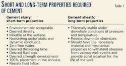
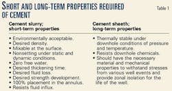
The cement system should meet both the short-term and long-term requirements imposed by the well's operational regime. Table 1 lists the typical short and long-term properties that are required of the cement system.
Traditionally, the industry has concentrated on the short-term properties that are applicable when the cement system is still in a slurry form. This effort is necessary and important for effective cement-slurry mixing and placement and has been the subject that researchers have studied for a number of years.
For most well conditions, a rigorous application of the best practices should improve the probability of effective cement slurry placement.
The long-term integrity, however, depends on the material and mechanical properties of the cement sheath, such as Young's modulus, tensile strength, and resistance to downhole chemicals.
Considering properties of the cement sheath for long-term integrity is critical if the well is subjected to large changes in stress levels.
If no fluid immediately migrates to the surface after placing the cement slurry in the annulus, cementing personnel may have satisfactorily designed for short-term properties such as density, static gel strength development rate, and fluid loss.
But recent experience has shown that after well operations such as well completion, pressure testing, stimulating, and producing, the cement sheath could lose its ability to provide zonal isolation.
This damage could create a path for formation fluids to enter the annulus, pressurize the well, and render it unsafe to operate. The damage could also result in premature water production and limit the well's economic life.
Examples of wells in which the cement sheath may be subjected to significant stress levels are:
- High-pressure (HP), high-temperature (HT), or HPHT wells.
- Deepwater wells.
- Gas-storage wells.
- Wells completed in weak, unconsolidated formations.
- Steam-injection wells.
- Producing wells converted into water injectors.
In most cases, engineers do not take the effect of well events on the integrity of the cement sheath into account when selecting the cement system. Studies on this particular subject have been relatively scarce.
Goodwin and Cook conducted an experimental study to evaluate the performance of different cements subjected to pressure and temperature changes.1 The study demonstrated that stiff cements or cements that possess a high Young's modulus are more susceptible to damage caused by pressure and temperature changes.
Benge, et al., recognized the unique elastic, resilient behavior of foam cements and successfully implemented them in the Gulf of Mexico, particularly in HPHT applications.2
Bosma, et al., simulated the mechanical responses of cement sheath based on a rigorous approach, such as finite-element analysis.3
Thiercelin, et al., applied analytical procedures to study the effect of cement mechanical properties.4
Gas storage wells
The natural gas industry commonly uses underground storage, in which natural gas is transferred from its discovery reservoir to other reservoirs that are usually closer to market areas, to store gas volumes until needed to meet market demand.
There are more than 400 underground storage sites in 27 states across the US and Canada. In Western Europe, underground gas storage has been an integral component of the gas marketing policy.
The oil and gas industry also occasionally uses storage as a conservation measure to prevent flaring when production rates exceed marketability.
Underground storage wells could undergo substantial changes in pressure and temperature during operations, and the stresses resulting from these operations could be detrimental to the integrity of the cement sheath.
Cement sheath damage consequence
Whether a well is drilled and completed for gas storage or for oil and gas production, the loss of cement sheath integrity could lead to the following:
- Loss of hydrocarbon reserves.
- Unsafe operations.
- Premature water or cap gas production.
- Unplanned remedial operations.
- Well shutdown to comply with government regulations.
Damage to the cement sheath, therefore, results in higher operating expenses and decreased recoverable assets.
Operators can use the cement-sheath design and evaluation tool to optimize the selection of cement systems to help reduce the probability of cement sheath damage under the particular well conditions and well events.
Problem setup
Researchers used a step-by-step approach to set up the problem in this study.
By considering the effects of the rock, cement sheath, and casing on one another, and by analyzing the effects of well events from well construction to hydrocarbons production, researchers determined the integrity of the cement sheath.
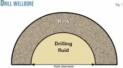
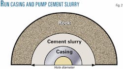
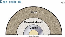
Fig. 1 depicts Event 1, which is drilling of the wellbore. In Event 2, the casing is run and the cement slurry is pumped (Fig. 2). And in Event 3, the cement slurry changes from a liquid to a solid from cement hydration (Fig. 3).
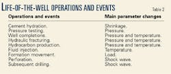
Table 2 lists examples of subsequent events, which consist of the typical operations in the lifetime of a well. Researchers used a finite-element-analysis technique to solve the problem of whether the cement sheath would maintain integrity.
Cement-sheath damage modes
For the cement sheath to continue providing zonal isolation, it must retain its integrity and the bond at the rock-cement and cement-casing interfaces should remain undamaged.
The cement sheath could lose its integrity if it cracks or the sheath undergoes plastic deformation.
This could allow radial and vertical migration of formation fluids into the annulus.
A cement sheath could crack, for example, due to cement shrinkage or if the casing expands because of pressure or temperature increase inside the casing.
Large differences in principal stresses cause compressive shear damage to the cement sheath. During volume shrinkage of cement slurry hydration, for example, tangential compressive stress decreases and can cause cracking.
Expansion of the casing, such as during pressure tests or hydraulic fracturing, increases the radial compressive stress and causes compressive shear damage.
Debonding at the cement-rock or cement-casing interfaces could lead to formation fluids vertical migration.
Engineers assume the cement sheath will behave linearly as long as the stress conditions do not exceed its tensile strength or compressive shear strength.
For undamaged cement material model, researchers adopted a Hookean model bounded by a smear-cracking model in tension and a Mohr-Coulomb model in compressive shear. The material model includes shrinkage and expansion of the cement system during hydration.
Cement sheath characterization
Technicians characterize the material behavior of different cement systems by performing tensile strength, unconfined and confined tri-axial, hydrostatic, and oedometer tests.
These are in addition to the conventional American Petroleum Institute (API) tests.
From these data sets, engineers determine Young's modulus, Poisson's ratio, and Mohr-Coulomb parameters and input the data for cement-sheath design and evaluation tool analysis to evaluate the integrity of the cement sheath.
Conventional oil well cement systems shrink, when they undergo a hydration reaction, which is due to the fact that the volume occupied by the end products is less than the volume occupied by the initial reactants.
This volume reduction or external shrinkage is typically on the order of 4%.
If during the cement hydration phase a fluid such as water is able to migrate from an external source, such as the formation, then this fluid could either partially or fully compensate for the volume reduction.
If water is not freely available, such as across shale sections, however, there could be a net shrinkage. An internal source, such as well-dispersed gas bubbles inside the cement, could fully compensate for the volume reduction of the hydrating slurry.
Well investigations
Researchers considered three wells in the study, with the objective of analyzing the integrity of the cement sheath during the typical operating envelope of the wells.
The workers considered three different cement systems, whose properties are given in Table 3, as possible candidates and their integrity determined by the cement-sheath design and evaluation tool analysis.
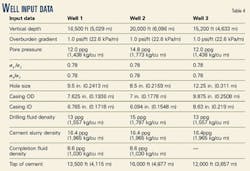
Table 4 gives the input data for the three wells, with Table 5 listing the events during which workers evaluated the integrity of the cement sheath.
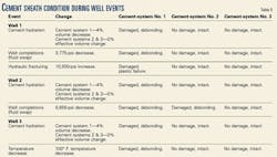
The well parameters, cement sheath, formation and casing properties, and well events were input into the model to analyze the condition of the cement sheath, with Table 5 also summarizing the results from the analysis.
Cement-system No. 1 was damaged in all the three wells because the system underwent 4% volume shrinkage during hydration and also the sheath was particularly stiff or brittle.
Cement-system No. 2 compensated for volume change during hydration and hence the effective volume change was zero.
The cement material, however, had similar properties compared to Cement-system No. 1.
Cement-system No. 3 compensated for volume change during hydration. It was also significantly less stiff or more elastic than Cement-systems No. 1 or 2.
Cement-systems No. 2 and 3 remained intact during all of the events in Well No. 1, but only the Cement-system No. 3 remained intact during all the events in Well No. 2.
The pressure decrease during the well completion event was 6,656 psi in Well No. 2, whereas it was only 3,775 psi in Well No. 1.
Cement-system No. 2 debonded at the rock-cement interface during the large pressure decrease occurring in Well No. 2, whereas Cement-system No. 3 had sufficient resilience to remain bonded.
Debonding at the rock-cement interface could serve as a conduit for formation fluid to migrate into the annulus and subsequently render the well unsafe and uneconomical to operate.
In Well No. 3, Cement-systems No. 2 and 3 were both intact when subjected to a temperature decrease.
In Well No. 2, of the three cement systems evaluated, only Cement-system No. 3 remained intact and could provide zonal isolation during the events that are occurring.
In Wells No. 1 and 3, Cement-systems No. 2 and 3 both remained intact.
In situations when the cement sheath remained intact, the cement-sheath design and evaluation analysis tool determines how far the cement sheath is from damage. Engineers can interpret this the risk of cement sheath or zonal isolation failure.
The final decision in choosing between Cement-system No. 2 and Cement-system No. 3 could depend on the sensitivity of the analysis to input variables, risk tolerance, and the economics over the life of the field.
From these investigations it is apparent that:
- The integrity of the cement sheath and effective cement placement is important to the safety and the economics of demanding gas-storage and oil and gas producing wells.
- To help reduce the risk of damage to the cement sheath, operators should use cement systems that compensate for hydration-volume reduction. Operators should also use cement systems that are less stiff or more resilient than conventional oil well cements.
- Cementing operations should effectively displace the drilling fluid from the annulus with the cement slurry.
- The integrity of a cement sheath depends on its mechanical properties, formation properties, and the well events.
The cement-sheath design and evaluation tool can effectively analyze the cement integrity.
Acknowledgments
The authors thank the Management of Halliburton, Shell International E & P, and TNO Building & Construction Research for their support and permission to publish this article.
References
- Goodwin, K.J., and Crook, R.J., "Cement Sheath Stress Failure," Paper No. SPE 20453, SPE Annual Technical Conference and Exhibition, New Orleans, Sept. 23-26, 1990.
- Benge, O.G., McDermott, J.R., Langlinais, J.C., and Griffith, J.E., "Foamed Cement Job Successful in Deep HTHP Offshore Well," OGJ, Mar. 11, 1996, p. 58.
- Bosma, M., et al., "Design Approach to Sealant Selection for the Life of the Well," Paper No. SPE 56536, SPE Annual Technical Conference and Exhibition, Houston, Oct. 3-6, 1999.
- Thiercelin, M.J., et al., "Cement Design Based on Cement Mechanical Response," SPE Drilling & Completion, December 1998, p. 266.
- De Witte, F.C., and Feenstra, P.H., "DIANA User's Manual Nonlinear Analysis," TNO Building and Construction Research, Delft, The Netherlands, 1998.
- Fjær E., et al., Petroleum-related Rock Mechanics, Elsevier Science BV, Amsterdam, 1996.
- Goodwin, K.J., McPherson, T.W., and Onan, D.D., "Elastomeric Composites for Use in Well Cementing Operations," Paper No. SPE 26572, SPE Annual Technical Conference and Exhibition, Houston, Oct. 3-6, 1993.
Based on a presentation to the Society of Petroleum Engineers Gas Technology Symposium, Calgary, Apr. 30-May 2, 2002.
The authors
Kris Ravi is project leader for Halliburton's WellLife cementing project and has been with the company for 12 years. He started with Halliburton as a research engineer in Duncan, Okla., and has held various positions including 3 years at the European Research Center in Holland. Ravi has an MBA degree and PhD in chemical engineering from Oklahoma State University, Stillwater.
Martin Bosma is a senior researcher in Shell International's Expandable Tubulars Team, dealing mainly with the zonal isolation aspects of this well-completion technology. Previously, he fulfilled various petroleum-engineering positions in Nederlandse Aardolie Maatschappij (NAM) and Sabah Shell Petroleum Co., Malaysia. He started his career with Shell 23 years ago in the company's exploration and production center at Rijswijk, The Netherlands, as a fracturing and well stimulation specialist.
Olivier J. Gastebled is a research engineer and consultant at TNO, Delft, The Netherlands. He received his diplôme d'ingénieur from INSA de Lyon, France, his MSc in structural engineering and his PhD from Heriot-Watt University, Edinburgh. His research interests include nonlinear modeling of concrete and rock.
