Coiled-tubing vacuum removes drilling-induced damage
A new technique uses concentric coiled tubing with a jet pump to remove drilling-induced damage from horizontal wellbores. The jet pump creates a pressure drop across the formation sandface that results in unwanted fluids, polymer residue, and drilling solids being transported to surface.
Horizontal wells increase production rates by targeting multiple zones, maximizing reservoir exposure, and reducing drawdowns to minimize premature water or gas coning problems. Many of these wells, however, include nonperforated completions that result in both mud-filtrate-induced formation damage and the incomplete removal of mud cake along the entire openhole. Formation damage and mud cake can impair productivity.
These wells have a significant risk for mud damage in the near wellbore region because of the extended exposure time of the horizontal wellbore to drilling mud.1-4 Thus, optimized performance of horizontal wells depends on preventing or removing drilling-induced damage.
Vacuum tool
Vacuum tools come in two sizes. A 3.75-in. OD tool for concentric strings of 1.25-in. coiled tubing inside a 2.375-in. coiled tubing, and a 2.5-in. OD tool for a concentric string of 1.0-in. coil inside of 2.0-in. coil.
The smaller tool allows entry into tighter completions and deeper wells because of its lighter weight.
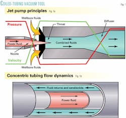
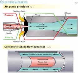
As shown in Fig. 1a,1 power fluid goes through the inner nozzle of the jet pump. At this point, a high-velocity jet forms because of the conversion of pressure energy to kinetic energy. The pressure decrease in the region immediately downstream of the inner nozzle draws in the wellbore fluids that mix with the power fluid in the pump throat, transferring energy to the wellbore fluids.
When the combined fluid enters the enlarged area of the diffuser, the conversion of the remaining energy to a sufficient static pressure lifts the fluids through the concentric coil annulus to the surface (Fig. 1b).1
One can change the nozzle and throat size based on flow rate and the pressure change (ΔP) desired. A friction reducer also helps increase the flow rate out of the well.
Cleaning out fill from horizontal wells typically is more difficult than from vertical wells. In horizontal wells, the coiled tubing on the low side of the wellbore disrupts the fluid-velocity profile, causing a stagnant area where gravitational forces dominate, and settling occurs.
If the fluid does not achieve critical velocity, a sand bed forms on the low side and will not be produced to surface, although the well will appear to be clean because returns are clean and the coiled tubing is at TD.
For concentric-coiled-tubing vacuum jobs with high-velocity jetting, the velocity of returning fluids is more than sufficient to carry all solids to the surface without any settling, even with dense or viscous materials. In fact, the annular velocity between concentric coiled tubings is two to three times greater than the 35-40 in./sec optimal conventional-coiled-tubing cleanout velocity for horizontal wells.
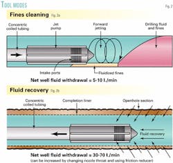
One can operate the vacuum tool in the following two modes:
- Solids (fines and sand) cleaning mode that directs a portion of the power fluid to the external jets to fluidize particulates (Fig. 2a).1
- Fluid-recovery mode for removing lost drilling mud. In this case, the external jets are shut off to maximize fluid production from the reservoir (Fig. 2b).1
The external jets also aid in loosening filter cake from the openhole walls and cleaning slots and openings in liners and screens.
Case histories
Canada and Venezuela have had many coiled-tubing vacuum jobs. Recently, jobs also have been done in the US, Australia, and Indonesia. These jobs have had a high success rate because the technique does not require exotic fluids, nitrogen, or high pump-in rates.
Venezuela has had more than 150 vacuum jobs during the last 2 years. Much of its oil production is from geologically young sands, having low reservoir pressure and poor consolidation. Most of these wells require sand control, and by far openhole slotted-liner completions are the most common because of their ease of installation, local availability, and low cost.
The coiled-tubing vacuum jobs are common in both the Orinoco heavy-oil belt and the Lake Maracaibo area.
The Orinoco belt encompasses more than 20,000 sq miles and contains about 1.2 trillion bbl of oil-in-place. The main oil-bearing zones are shallow Tertiary sands, with 2-17 darcy permeabilities, now being developed with a mix of horizontal and multilateral wells.
From a wellbore cleanup point of view, challenges in these slotted-liner horizontal wells include no isolation behind pipe, highly deviated boreholes, long lateral reach, low reservoir pressure, and viscous oil.
The Miocene and Eocene formations near Lake Maracaibo also are prone to sand production. In this area, operators have tried many sand-control techniques over the years. For example in the 1950s, this area was the first to use the sand-oil-squeeze, which is the precursor of the frac pack.
But, as in the Orino co belt, the most common sand-control technique in this area is slotted liners.
The concentric-coiled-tubing vacuum tool has been run in a variety of wells with complex damage problems. Three types of vacuum jobs identified to date based on three distinct damage mechanisms are:
- Fluid removal.
- Solids (filter cake) removal behind pipe.
- Solids removal inside liner.
A single well having more than one type of damage was common in Ven ezuela jobs.
Fluid removal
Losing fluids during drilling is a common problem in low-pressure Orinoco belt reservoirs. To improve well cleanup, operators have recognized the need to remove lost fluids as soon as possible after drilling stops. The short and long-term impact of this fluid on well production rates has been a major concern.
Most companies drill these wells from pads, with up to 16 wells, in a batch drilling mode that reduces drilling time, rig moves, and surface location costs. This means that often there is an extended period of time between the well completion and start of production.
Extended exposure times, such as 6 months, to lost drilling fluid may reduce well productivity and is a critical concern. Cleanups relying on electric submersible pumps (ESPs) to lift lost drilling fluid can be time-consuming, damage the pump, and leave water behind, especially near the toe of the well.
This water can remain in the well for years creating flow problems or causing slugging in initial production. Extended formation exposure to lost drilling fluids also may cause water blocks, emulsions, or relative permeability changes in the near well- bore.
Overbalanced drilling by 200-300 psi and extended time between completion and production combine to increase the amount of water-based fluids lost to the formation.
To recover the fluid with a vacuum tool, one runs it to TD to establish maximum suction. Any obstructions along the way, as noted by a weight-indicator decline, can be removed by cycling the tool to the solids removal mode.
Shutting down surface pumps and restarting them cycle the tool.
By changing the throat of the jet pump, one can adjust the suction rate and ΔP. The Orinoco jobs use the largest size throat and nozzle configuration and special friction reducers to maximize fluid removal rate of up to a net fluid outflow rate of 1.48 bbl/ min.
After being left stationary, the tool is pulled out of the hole when one observes a 100% oil cut at surface. The speed for pulling out the tool is adjusted based on keeping at least 90% oil in the fluid returns. In other words, the tool drags a column of oil to surface, while it is removing unwanted lost drilling fluid.
In one Orinoco field, the operator used the tool in about 40 wells with slotted-liner completions. Well completions ranged from single horizontals to multibranch fishbones. The removed fluid from some wells consisted of only drilling mud while from other wells it contained mud, fines, and oil emulsions.
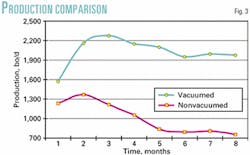
Compared to similar conventionally cleaned offset wells in the same area, the coiled-tubing vacuuming increased production by more than 30%,2 and in one case, the technique removed more than 5,000 bbl of lost fluid from a single well.
Average hole volumes of fluid removed from the 40 wells were 2.45 from single horizontals, 3.2 from dual horizontals, and 3.2 from multilaterals. In the case of multilaterals, several jobs revealed that some laterals were not contributing to production prior to cleaning. After a vacuum treatment, these wells had improved production, indicating that all laterals were producing.
Solids behind pipe
Long horizontal wells require operators to pay more attention to cleanliness because the reservoir surface area is much greater and susceptible to damage. The industry has developed drill-in fluids to address this issue. These fluids create a low permeability, removable filter cake on the wellbore that inhibits drilling fluid invasion and does not damage the formation.
These fluids typically contain bridging material, such as sized calcium carbonate (CaCO3), and a combination of starch and polymers to build the filter cake
Weak acids or other fluids can clean off these cakes, but the complicating matter is that the drilled formation solids that mix into the cake, especially on the low side of the borehole, generally are not soluble in acid.
Two identified mechanisms of filter cake failure or detachment are: pinhole failure and break-away failure. Pinhole failure causes much of the cake to be left on the rock face, thus reducing well productivity.
Laboratory data expresse filter cake cleanup in weight percent or on retained permeability.
In coiled-tubing vacuum jobs, the tool applies a ΔP across the entire sandface sufficient to remove all cake deposits. The job incorporates an acid if CaCo3 is in the drill-in fluid.
One operator of an Orinoco field found filter cake removal difficult. The field contains poorly consolidated Miocene sand reservoirs at 3,000-3,500 ft TVD, with an average 275-ft thickness and 10-12 darcy permeability. The drill-in fluid included CaCO3 to help create a filter cake.
The field produces a heavy oil with an average 5,500-cp viscosity that is made pumpable with the addition of a light diluent. A typical horizontal well has 133/8-in. surface casing, 95/8-in. casing to top of reservoir, and a 7-in. slotted liner throughout the horizontal section. Production is through 41/2-in. tubing that has an ESP or progressing cavity pump (PCP) set near to the 95/8-in. casing shoe and a 1.9-in. side string for downhole diluent injection.
In the field, the 300-psi overbalanced drilling and long drilling times result in a filter cake on the openhole section that contributes to wellbore skin damage. Furthermore, the 2,000- 4,600 ft horizontal sections on new wells make conventional cleanup procedures inefficient.
The operator, therefore, started using the concentric-coiled-tubing vacuum tool.
The tool applies a point-load creating a pressure influenced zone that strips filter cake from the open hole. These jobs run the tool in hole at minimum speed until the kick-off point. At this point, the tool is switched to a sand vacuuming mode for solids removal before it is run to TD.
During the tool's run to TD, the procedure includes stopping the tool and cycling it if the observed return fluid has sand or mud fines greater than 1%. At TD, the same tool mode is kept until the sand or mud fines disappear in surface samples.
In the next step after recovering all of the solids, one switches the tool to a fluid recovery mode, sets the injection rate for a maximum drawdown, and leaves the tool stationary while testing the returns. Tool pull out of the hole starts when the observed fluids are nearly 100% oil and contain no solids. At the start, tool pull out is slow to allow the entire liner to be cleaned sufficiently.
In these jobs, the vacuum tool removed loose material, filter-cake polymers, an average of 780 lb of formation fines and fine drill cuttings, and an average of 380 lb of CaCO3.
The technique allowed the wells to be ready for oil production in a shorter time than conventional cleanup techniques in which wells often produce at a high water cut for extended periods to special separators. With the vacuum tool the operator can immediate produce the oil. In fact, after only 2 hr, the vacuumed wells produced enough oil so that it was unnecessary to align them to special separators.
The vacuumed wells produced for an average 2 days with a water cut compared to the 14 days for the non-vacuumed wells.
Fig. 3 shows the performance of 25 wells, all completed in the same reservoir. For the vacuumed wells, average initial production is 20-30% higher and after 8 months the vacuumed wells kept their initial production, while the other wells declined rapidly.
In wells with much filter-cake damage, the operator saw an initial production improvement greater than 30%.
The coiled-tubing vacuum technique also has the benefit that one can calculate a productivity index (PI) during the job throughout the entire reservoir section. This requires the bottomhole assembly to have a pressure and temperature memory gauge that records depth vs. time. This data combined with well return rate data, which is measured throughout the job, allows one to calculate a PI.
One can take further remedial action if the PI indicates that a zone is not contributing to well production.4
Many jobs in Venezuela have benefited from PI calculations.
Solids removal inside liner
In the past, coiled tubing or junk baskets on jointed pipe have cleaned out many wells that were sanded up or became blocked. These jobs are more complicated in deeper and horizontal wells.
For these more difficult jobs, the use of conventional coiled tubing requires one to use high pump rates and special viscosified fluids that suspend and push solids to surface in the annulus between coiled tubing and liner. This normally places an overbalance on the reservoir and often jobs fail because insufficient annular velocity causes fluid losses to the formation.
In some attempts, the cleanout jobs used nitrified fluids, which are expensive and operationally difficult to use. Also, horizontal well cleanouts require a large volume of nitrogen, which can be logistically impossible to obtain.
Conventional coiled-tubing cleanouts also may fail at the liner-to-casing interface. This junction typically has a large increase in annular size, such as 7-in. liner to 95/8-in. casing, that creates a dead zone in terms of annular velocity. Solids from the liner section lose velocity and congregate at the liner-casing interface.
A well may appear to be clean because returns at surface are clear, but solids in the dead zone may fall back to the bottom after the coiled tubing is pulled above the liner hanger;
Venturi junk baskets only can remove a limited amount of fill in one run. These jobs often require several runs to clean fill and may take more than a week. The baskets also are prone to be jammed or stuck in the hole.
Western Venezuela has several depleted medium to heavy-oil fields with reservoir pressures as low as 0.13 psi/ft. Several vacuum jobs in these older depleted wells have confirmed that sand fill prevents production. In some cases, the entire liner was found full of solids.
Vacuum jobs were able to remove fines fill from vertical gravel-packed wells. In some cases these wells already had been cleaned with conventional coiled tubing.
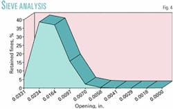
Engineers require sieve analysis to size gravel and slot size. The analysis also is used after the well is completed to determine the efficiency of a sand-control completion.
The procedure includes taking samples of solids continuously from a special settling tank and then cleaning them before doing laboratory sieve analysis, which in some cases involves wet chemistry analysis. This sieve data can reveal problems in the completion hardware or design, such as Fig. 4, that is a sieve analysis from a well with 0.20-in. slots.
Samples from vacuum jobs are more representative of the size of particles passing through the slots because these samples are not bailed or taken from surface catchers. On several jobs, the operator determined that slot erosion had occurred.
One well with a 0.20-in. slotted liner produced 30,000 lb of solids during a job. This was more than the liner volume of the well and indicates that erosion or some other mechanical failure occurred downhole.
Wellbore stimulation
Even though the tool creates a vacuum in a restricted annular area in front of the ports, the tool lets the annular resident time for the circulating fluid to be adjusted for specific conditions.
Also, one can dress the tool so that not all the injected fluid injected is recovered. In this way, acids or other fluids could be incorporated for near-wellbore stimulation of the complete interval instead of for just sand-damage removal.
Pumping on both sides of the concentric coiled tubing allows for 100% bullheading into the formation. This procedure bypasses the jet tool and pushes fluid directly into the formation.
The jobs normally include completion brines or water with a friction reducer, but one can use other fluids such as acids, enzymes, and solvents to remove near-wellbore damage.
Oil with solvents can be used as the circulating fluid in low-pressure reservoirs with organic deposits such as asphaltenes or paraffines. To obtain higher flow rates, one can gell these fluids with phosphate ester-type material to produce a shear thinning fluid with lower friction and enhanced solid-support capacity.
The jobs can include water-base fluid with terpene-type solvents instead of organic solvents in reservoirs with enough drive energy. Also brines can be gelled with viscoelastic surfactants to reduce friction pressures and enhance solid-support capacity. This will improve pump efficiency and generate higher cleaning rates.
Operators typically drill horizontal wells with drill-in fluids containing one or two polymers and soluble granular materials. The filter cake created by this fluid is difficult to remove from the entire interval.
The only removal methods that have shown a good success rate are exotic soaking treatments with consecutive stages of enzymes and weak acids. The vacuum tool allows one to use stronger acids that will instantly dissolve carbonate particulates as well as polymers such as starch, cellulose, and guar derivatives.
One can treat other more acid resistant polymers like xanthan and partially hydrolyzed polyacrylamide (PHPA) materials with strong specific enzymes solutions or hypochlorite solutions, respectively.
The tool design also has allowed it to clean sand and at the same time to spot adsorbing chemicals such as scale inhibitors, organic dispersants, and surfactants in the near wellbore.
Acknowledgment
The authors thank the management of Chevron Texaco E&P Technology Co. and BJ Services Co. for granting permission to publish this article.
References
- Heikkkinen, B.K., Kuchel, M.P., Stang, Q.S., Misselbrook, J.G., Sudol, T.A., and Lillico, D.A., "Drilling Damage Removal Using Multi-Point Drawdowns Along the Horizontal Wellbore," Paper No. SPE 46011, 1998.
- Clancy, T.F., Falk, K.L., and Duque, C.A., "Concentric Coiled Tubing Well Vacuuming Technology for Complex Horizontal Wells in Eastern Venezuela," Paper No. SPE 60696, 2000.
- Falk, K.L. and Fraser, B., "Sand Cleanout Technology for Horizontal Wells," CIM Paper 95-57, 1995.
- Figueroa, J., Hibbeler, J., Duque, L., and Perdomo, L., "Skin Damage Removal Using Coiled-Tubing Vacuum: A Case Study in Venezuela's Orinoco Belt," Paper No. SPE 69532, 2001.
The authors
Syed A. Ali is a senior staff research scientist for ChevronTexaco E&P Technology Co., Houston. He specializes in sandstone acidizing, formation damage control, rock-fluid interaction, mineralogy, and oil-field chemistry. Ali has an MS from Ohio State University and a PhD from Rensselaer Polytechnic Institute. He is a member of SPE.
Jeffrey C. Hibbeler is the country manager for BJ Services Co. in Rio de Janeiro. He has been with BJ for 13 years in a variety of technical and management positions.. Hibbeler has a BS in engineering geology from Texas A&M University. He is a member of SPE.
Gino F. Di Lullo is a technical and marketing manager for BJ Services Co. in Rio de Janeiro. He previously worked for IBM and Dowell Schlumberger in Brazil. Di Lullo has a BS in electrical engineering from the Catholic University of Petropolis-Brazil. He is a member of SPE and a registered professional engineer in Brazil.
