Fiber optic technology holds potential for microseismic monitoring
Julie Shemeta
MEQ Geo Inc.
Denver
Emerging fiber optic technology could revolutionize an already important geophysical technology, microseismic monitoring, for oil and gas operations. The acquisition of microseismic data for hydraulic fracture monitoring has seen numerous step changes.
Microseismic monitoring started with the ability to collect microseismic waveforms from a single 3-component geophone deployed on a wireline in the 1980s. Advancements during the last 15 years include multilevel geophone wireline strings of 8-50 sensors spaced at 50-100 ft intervals with both conventional and fiber optic wireline. Additionally, microseismic data is collected using large arrays of geophones on the surface and in shallow boreholes.
The use of fiber optic cable, typically deployed in wellbores behind casing, is in the initial stages of development for use in microseismic monitoring.
Fiber optic systems deployed in wellbores for distributed temperature sensing (DTS) measurements and distributed acoustic sensing (DAS) have been in use for more than 10 years. Operators use fiber optics for various wellbore surveillance surveys such as stimulation monitoring, flow allocation, well-interference testing, and well integrity.
A laser and interrogator on the surface measures the scattering of light along the fiber as the fiber deforms during deployment. Different types of scattering allow for different measurements, such as temperature (DTS) or strain (DAS). 1
More recently, fiber optic DAS systems are being used for the acquisition of microseismic surveys. The fiber can be deployed in wells 5,000 ft or longer, either horizontal or vertical, allowing for an expansive glimpse of previously unseen microseismic waveforms.
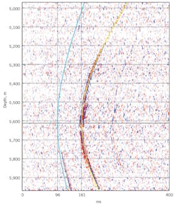
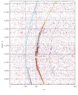
The upper figure shows a microseismic event recorded on a Silixa Ltd. fiber optic cable in a horizontal observation well during a well stimulation. The lines mark the P-wave arrival (blue) and the the S-wave arrival (red). (Fig. 1). Photo from P. Richer and G. Elesztos, Silixa.
Fig. 1 shows a DAS image from a microseismic event recorded in a horizontal observation well about 1,500 ft from the stimulation well.
Complex microseismic waveform details displayed on DAS microseismic provide much more information than a conventional 3C clamped borehole geophone array or the low signal-to-noise surface array data with 1,000 plus surface geophones.
Good coupling with the formation is essential to the collection of microseismic signals, as is the case with borehole geophones. Fiber deployments behind pipe, cemented into the formation, have shown the most promise.
A hydraulic fracture monitoring project in the Meramec shale used both conventional borehole geophones and DAS. While not as sensitive as the conventional geophone, the DAS system was able to detect events down to magnitude -2, and as much as 1,500 ft from the observation well with fiber.2
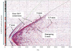
A Pioneer Natural Resources study discusses DAS data collection from the Permian basin, combining it with DAS strain, DTS, downhole pressure, radioactive tracers, and 3D-4D vertical seismic profile (VSP) data during a hydraulic fracture.3 Fig. 2 shows a DAS image in a vertical observation wellbore during a hydraulic fracture in Pioneer’s study.
The vertical axis shown in this DAS recording of a microseismic event during a hydraulic fracture is 4,400 ft MD in a vertical well with gamma ray log for reference on the far left. The various phases of the microseismic event are labeled as reflected energy and converted P-wave and S-wave phases (Fig. 2). Reprinted with permission from the Unconventional Resources Technology Conference (URTeC) 3, whose permission is required for further use. Modified from URTeC 2695282.
One limitation of DAS acquisition is the unidirectional nature of the DAS measurement and the limitation of the fiber in collecting information when the signal is traveling transverse to the fiber.1
The lack of azimuthal information limits the ability to determine microseismic event location relative to the wellbore, creating a location ambiguity. The location ambiguity is potentially solvable with fiber in both the horizontal and deviated section of a wellbore,4 or the use of multiple fiber deployments able to co-detect microseismic activity, or the co-deployment of conventional geophones with the fiber optics.
Collection of multicomponent DAS using a helical fiber optic design is a potential future advancement of this exciting new technology.5
Depending on the fiber optic cable deployed, DTS and strain measurements can be made in conjunction with DAS, allowing for details in flow, perforation performance, flow back, and stimulation optimization in conjunction with the microseismic survey.
References
1. Lumens, P., “Fiber-optic sensing for application in oil and gas wells,” Eindhoven University of Technology, Endhoven, Netherlands, PhD thesis, Jan. 1, 2014.
2. Karrenbach, M., Ridge, A., Cole, S., Boone, K., Kahn, D., Rich, J., Silver, K., and Langton, D., “DAS Microseismic Monitoring and Integration with Strain Measurements in Hydraulic Fracture Profiling,” Society of Petroleum Engineers, American Association of Petroleum Geologists, and Society of Exploration Geophysics URTeC, Austin, Tex., July 24, 2017.
3. Hull, R., Meek, R., Bello, H., and Miller, D., “Case History of DAS Fiber-Based Microseismic and Strain Data, Monitoring Horizontal Hydraulic Stimulations Using Various Tools to Highlight Physical Deformation Processes (Part A),” SPE, AAPG, and SEG, URTeC, Austin, Tex., July 24, 2017.
4. Webster, P., Molenaar, M., and Perkins, C., “DAS Microseismic,” CSEG Recorder, Vol. 41, No. 6, June 2016, pp. 38-39.
5. Ning, I., and Sava, P., “High-resolution multi-component distributed acoustic sensing,” Geophysical Prospecting,” Vol. 66, No. 6, July 2018, pp. 1111–1122.
The author
Julie Shemeta ([email protected]) is president and founder of MEQ Geo, an independent microseismic consulting company based in Denver. Her experience includes conventional oil and gas development and geothermal energy, specializing in microseismic applications.


