Study reveals variables that affect cement-plug stability
A recent operating-service company study provides greater understanding of slurry movement after placement in the wellbore.
This work provides an improved explanation of the relationships between cement-plug stability and the following factors:
- Wellbore angle-vertical, horizontal, or deviated.
- Spotting fluids and wellbore fluid rheologies and densities.
- Hole diameter.
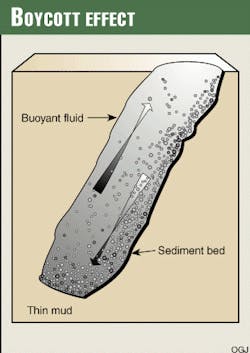
Cement-plug instability can be attributed to specific slurry movements, such as the Boycott effect, in which heavier fluids slide as a mass to the lower side of an inclined borehole.
Thus, the knowledge acquired from this study should allow drilling personnel better to tailor cement-plug designs for specific hole conditions.
Previously, plug-cementing successes and failures appeared randomly. Existing publications provide general recommendations without specific details. Thus, many near misses and inconsistencies experienced during plug-cementing operations remain unexplained.
Plug cementing
Plug cementing is an essential operation performed under a variety of well conditions. A cement plug can be required temporarily or permanently at any time during the life of a well. Generally, cement plugs are set for the following four purposes: sidetracking, lost-circulation control, zonal isolation, and well abandonment.
In addition, cement plugs are often required by government agencies that regulate drilling, production, and abandonment activities.1
The original intent of this study was to examine horizontal plug-setting conditions. Supplementary data, however, were also collected for vertical and deviated wellbores. Tests were carried out with 18 and 30-ft Plexiglas and steel models having diameters of 4.5, 6.0, 8.5, 12, and 16 in.
Cement placement was conducted with a flow diverter attached to the end of a tailpipe. This mechanism was designed to help prevent the slurry from being jetted downhole. Subsequent tests were performed with steel casings.
These destructive tests helped verify the visual observations of the Plexiglas work and allowed observers to examine cross sections of the set plugs. All models were attached to movable skids.
The skids holding the open end of the models were placed on elevated platforms of varying heights, providing the desired hole angles. Because these tests were conducted at atmospheric pressure and temperature, actual applications will require all rheological properties to be simulated at bottomhole circulating temperatures.
Engineers grouped the drilling fluids used for these tests by density, rheology, and gel-strength development. After the mud was prepared, it was pumped into the models and kept static for 1 hr, which allowed adequate gel-strength development.
Fluid density and rheology were measured with a pressurized mud balance and a rotational viscometer. Engineers performed most tests with a 16.4-ppg cement slurry. Limited tests were conducted with a 12.4-ppg, prehydrated bentonite slurry.
All slurries were mixed in a conventional recirculating mixer equipped with a radioactive densometer. Technicians verified slurry densities in the laboratory and rheology was measured with a rotational viscometer. All fluids were placed in the models by means of a centrifugal pump.
Horizontal wellbores
Based on the cumulative test results, setting plugs under horizontal conditions proved to be the least challenging when general precautions were taken. For the 4.5 and 6.0-in. models, a mud-yield point of 30 lb/100 sq ft in an 8.7-ppg mud sufficiently prevented severe slumping.
For the 8.5-in. model, a mud yield point of about 40 lb/100 sq ft was required. Testing indicated that the yield point of the mud could be decreased as the density differential between the mud and the cement was decreased.
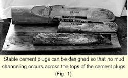
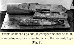
Tests run with identical cement slurries and mud densities, but with decreased gel strengths, provided slightly longer slump profiles. Stable cement plugs, however, were achieved with no mud channeling across the tops of the cement plugs.
The test section in Fig. 1 shows the results of a typical test performed in a horizontal wellbore.
Deviated wellbores
Deviated wellbore testing produced results similar to those reported by prior workers.2 One test set showed the mud rheology typical of normal drilling operations cannot support a cement slurry with a significantly greater density.
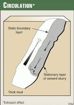
For deviated wellbore tests, the Boycott effect became apparent with thin muds but not with thick muds. Instead of sliding down the bottom of the model as with the Boycott effect (Fig. 2), the slurry formed a stationary layer against the bottom of the model, resulting in a crust at the cement-mud interface.
This crust was constantly extruded from within, continuously forming a new interface as the mass of slurry progressed down the model (Fig. 3). In addition, tests conducted at angles from 45 to 75° indicated that plug stability depends on the following:
- Reducing the density differential between the drilling fluid and the cement. For angled wellbores, plug stability is difficult to achieve if the spotting fluid is approximately 3 ppg heavier than the mud in place, regardless of mud rheology.
- Increasing the yield point of the drilling fluid below the intended cement plug. This practice helps improve the support of the cement plug. However, the weight difference between the slurry and the wellbore fluid still greatly contributes to downhole plug stability.
- Placing a reactive spacer between the cement and the mud. Incompatibility between the cement and the mud does not always provide sufficient support for a cement plug. A properly placed reactive spacer, however, did increase the stability of the plug at the angle tested.
Vertical wellbores
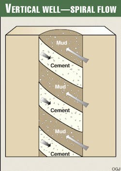
As expected, vertical tests confirmed existing data. The flow or swapping mechanism observed for these models, however, was different from prior tests. Rather than sliding or extruding down one side of the wellbore, as is typical with the Boycott effect, the slurry unwound or roped from the bottom of the cement plug in a clockwise pattern (Fig. 4).
This movement continued until the leading edge of the slurry reached the bottom of the model. For thinner muds, the slurry began to pile up at the bottom of the model until a state of equilibrium was reached. This movement resulted in a double helix of cement that reached from the bottom of the model upward, forming a small but competent cement cap at the top.
For tests involving thin muds, slurry movement could only be stopped when the cement reached the bottom of the model and began stacking. As the yield point of the mud was increased, the stacking effect became less pronounced.
This change in the stacking effect might not have been the result of an increased yield point. It may have resulted when the equivalent density of the mud-cement mixture in the rathole approached a critical point that slowed or stopped further reductions in the volume of the competent slurry above.
Job considerations
Additional research indicates that successful plug cementing operations require the same degree of planning as primary cementing jobs. Therefore, before performing cement plug jobs, operators should consider the following:3
- Temperature estimates are often adjusted for increased safety. This practice, however, can result in over-retarded cement.
- Modified cementing and washing diverter tools can provide excellent mud displacement for entire plug intervals.
- Many operators do not consider variables such as fluid loss, gas migration, and rheology, when designing plug slurries. Under-designed plug slurries, however, often perform poorly.
- High-density slurries are often used for reducing slurry settling. Settling solids, however, are primarily controlled by yield point and gel strength. Plug stability can often be achieved with normal to slightly densified slurries when good placement techniques are used.2
- Coarse sand is often added to cement plugs for providing increased drilling rates. Historically, coarse sand has often been added to cement plugs to make the plugs harder and therefore easier to whip off of. No evidence suggests, however, that coarse sand provides this effect. In addition, coarse sand can be difficult to keep suspended and can create settling problems.
- Only three wellbore conditions normally require excessive slurry volumes for producing balanced plugs: contaminated wellbores, oversized-noncalipered holes, and wellbores that exhibit downward movement.
- Thixotropic slurries often create mud-filled voids, causing cement plugs to drill "soft."
Test application
Based on the tests described in this study, a method was devised for formulating successful cement plugs. For improved plug stability, refer to the following steps, which correspond to Tables 1 and 2.
- Determine the hole diameter and angle where the cement plug will be set.
- Find the cell in Table 1 that best relates to these values. For values not provided in Table 1, round up or down.
If the hole diameter is more than 50% between two of the values provided in Table 1, round up to the next highest diameter.
Do the same for hole angle. For example, a hole diameter of 51/2 in. would be rounded to 6 in., and a hole angle of 40° would be rounded to 45°.
If the hole diameter is less than 50% between two of the values provided in Table 1, round down to the next lowest diameter.
Do the same for hole angle. For example, a hole diameter of 7 in. would be rounded to 6 in., and a hole angle of 50° would be rounded to 45°. - After determining the alpha values from Table 1, use Table 2 to determine wellbore and cement properties.
In the following example, an operator needs to set a cement plug to kick off the hole where the hole angle is 55° and hole diameter is 121/4 in. Based on the values provided in Table 1, the hole angle should be rounded to 60° and hole diameter should be rounded to 12 in.
The alpha values representing these conditions are determined as follows: VL (very low), M (minimum), and M (maximum).
Based on these alpha values, wellbore and cement properties are determined from Table 2. According to Table 2, the density difference between the wellbore fluid and the cement should not exceed 1 ppg. The wellbore fluid's yield point should be greater than 60 ft-lb/100 sq ft and its 10-min gel strength should be greater than 20 ft-lb/100 sq ft.
Therefore, assuming a cement density of 15 ppg, the wellbore fluid should have a density of >14 ppg, a yield point of >60 ft-lb/100 sq ft, and a 10-min gel strength of >20 ft-lb/100 sq ft. If any of these criteria are not met, the cement plug will swap with the wellbore fluid.
Results
This project provided a better explanation of what previously seemed to be random plug success and failure. For example, even after using excessive slurry volumes, some operators reported top plugs that achieved lower levels than anticipated.
Tests performed during this study duplicated such problems and revealed the causes. In this case, cement was circulated in situ into the rathole. Mud was reaching the cement plug during pumping operations and during swapping operations performed after pumping had ceased.
As a result, the competent plug was shorter and exhibited a longer, lower section of contaminated, poor-quality cement. Based on this study, the following statements can be made:
- Successful cement plugs depend on the relationship between hole angle, hole size, yield point, the gel strength of the supporting mud, and the density differential between the cement and the supporting mud.
- Cement plugs can be placed most easily in horizontal wellbores.
- In deviated wellbores, cement-plug instability is caused by the Boycott effect or extrusion. In vertical wellbores, it occurs when the slurry ropes or spirals through the mud.
References
- Smith, D.K., et al., Worldwide Cementing Practices, American Petroleum Institute, Third Edition Washington, D.C., 1981.
- Smith, R.C., Beirute, R.M., and Holman, G.B., "Improved Method of Setting Successful Cement Plugs," Journal of Petroleum Technology, November 1984, pp. 1897-1904.
- Heathman, J., "Advances in Cement Plug Procedures," Journal of Petroleum Technology, September 1996, pp. 825-31.
The Authors
David G. Calvert is associate engineering advisor for Mobil Exploration & Producing Technical Center. He joined Mobil in 1979, specializing in acidizing, cementing, fracturing, lost-circulation, and sand-control technologies. Calvert holds a degree in chemistry from Northeastern State University, Tahlequah, Okla.
James F. Heathman is a technical analyst for Halliburton's Houston Business Development Area, specializing in cementing and conformance technology. He has held a variety of engineering assignments since joining Halliburton in 1987.
Heathman holds BS and MS degrees in petroleum engineering from Louisiana Tech University, Ruston and an MBA from Oklahoma State University, Stillwater.
James E. Griffith is the global technical advisor for zonal isolation technology at the Halliburton Energy Services Inc. Technology Center, Duncan, Okla. Before joining Halliburton, he worked as a production engineer for Chevron USA and as a drilling engineer for an independent production company.
Griffith holds BS and MS degrees in petroleum engineering from the University of Oklahoma, Norman, and an MBA from Oklahoma City University.
