Design guide developed for buried pipelines crossing active faults
An analysis of the response of buried continuous pipelines to active faults has led to development of a design guideline for both onshore and offshore pipelines at fault crossings.
A fault movement can be resolved into an axial component (parallel to the pipe axis), a lateral component (perpendicular to the pipe axis) in the horizontal plane, and a vertical component.
When subjected to bending (lateral or vertical component) and axial tension force (axial component), a pipeline is likely to fail in tensile rupture. The analytical approach by Kennedy is recommended for calculating the maximum tensile strain in the pipe.1 When subjected to bending and axial compression, a buried pipeline is likely to fail in wrinkling (local buckling) and a finite-element method is recommended for calculating the maximum compressive strain in the pipe.
This discussion focuses in detail on both methodologies and presents two design examples as illustration. Several countermeasures are discussed, and consideration priority is given in selection of countermeasures for a typical design case.
Fault research
Surface faulting has accounted for many pipe breaks during past earthquakes. For example, during the 1971 San Fernando, Calif., earthquake, only 0.5% of the area was influenced by surface faults, yet the fault movement resulted in more than 1,400 breaks in water, natural gas, and sewer pipelines.2
Damage to gas and oil pipelines can cause tremendous losses, especially the secondary loss related to service interruption, fires, explosion, and environmental contamination.
Research on disaster mitigation of pipelines has covered decades. For example, Kennedy developed an analytical approach for estimating maximum strains of an underground pipeline subject to faults in bending and axial tension.2
O'Rourke and Liu developed a numerical model to analyze pipe response to fault offsets and compared their numerical results with the results from other analytical approaches. They concluded that Kennedy's analytical solution is the best available for pipe response to strike-slip faults primarily in tension.
The American Society of Civil Engineers developed guidelines for the seismic design of oil and gas pipeline systems.3 The guidelines provide valuable information on seismic design considerations for onshore pipelines and on force-deformation curves of the pipe-soil interactions for pipelines buried in both clay and sand.
In its fault-crossing design, ASCE present two analytical approaches, but they predict maximum pipe strains with significant difference.
This article presents a design guideline developed for both offshore and onshore pipelines at fault crossings, using Kennedy's model to calculate maximum tensile pipe strain and a FE model to calculate maximum compressive pipe strain.
Fault type; offset components
An active fault is a discontinuity between two portions of the earth's crust along which relative movements can occur. There are three types of faults: strike-slip fault, normal fault, and reverse fault.
In a strike-slip fault the predominant motion is horizontal, which deforms a continuous pipe primarily in tension or compression depending on the pipe-fault intersectional angle.
In normal and reverse faults, the predominant ground displacement is vertical. A normal fault deforms a horizontal pipe primarily in tension, while a reverse fault deforms a horizontal pipe primarily in compression.
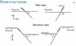
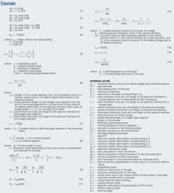
Fig. 1 shows a pipeline crossing a fault with an intersectional angle, ß, and a fault dip angle, Ψ For a pipeline crossing a strike-slip with a horizontal fault offset, δs, Equation 1 (shown in accompanying Equations box) gives the axial component along the pipeline, Δx, and the lateral component perpendicular to the pipeline, Δy.
For a pipeline crossing a normal or reverse fault with fault offset, δy, Equation 2 gives the horizontal component along the pipeline, Δx, the horizontal component perpendicular to the pipeline, δy, and the vertical component, Δz.
For a fault having both δs and δp, Equation 3 gives the three components Δx, δy, and Δz. In Equation 3, δp is positive for a normal fault and negative for a reserve fault, and δs is positive for a right strike-slip fault and negative for a left strike-slip fault.
Fig. 1 shows the coordinates and definition for the intersection angle and fault dip angle.
Failure mode, criteria
A plastic seismic design for pipelines at fault crossings is acceptable because earthquakes happen infrequently and fault movements are conservatively estimated based on a possible maximum earthquake magnitude for a 100-500 year of return period.
Even though the strongest earthquake occurs, the pipeline will be in plastic range but will not fail. The pipe service can be sustained and a post-earthquake treatment may be needed to relieve pipe stresses.
There are three failure modes for a pipeline subjected to active faults: tensile rupture, local buckling, and beam buckling.
In tensile rupture, a buried steel pipeline is primarily in tension when subjected to a normal fault or strike-slip fault with β ≤ 90°. When strained in tension, corrosion-free steel pipe is very ductile and capable of mobilizing large strains. The strain associated with tensile rupture is about 4%.4
Often an ultimate tensile value of 4% is used, beyond which the pipeline is considered to have failed in tension. As an increased safety level for an offshore pipeline, 1% tensile strain may be used as the seismic design limit due to the difficulty to access an offshore pipeline and detriment long-term effects of a highly strained pipe.
Local buckling (wrinkling) refers to local instability of pipe wall when loaded in compression.
After initiation of local shell wrinkling, all further geometric distortions caused by ground deformation tend to concentrate at the wrinkle. The resulting large curvature in the pipe wall often then leads to circumferential cracking of the pipe wall or leakage. A buried steel pipeline is primarily in compression when subjected to a reverse fault or strike-slip fault with β > 90°.
Regarding the failure criterion for local buckling, Hall and Newmark suggest that compressional wrinkling in a pipe normally begins at a strain of 1/3 to 1/4 of the theoretical value of 1.2t/D based on prior laboratory tests on thin-wall cylinders.4 Here the midpoint of the range established by Hall and Newmark is recommended for the onset of wrinkling (Equation 4).
As an increased safety level, a maximum strain of 0.5% may be used as the seismic design limit for an offshore pipeline in compression.
Beam buckling of a pipeline is a state of structural instability in which the pipeline undergoes a large transverse displacement. Since the displacement is distributed over a large distance, the pipe strain is not large and often the pipeline does not fail.
Beam buckle may occur for a pipeline with insufficient vertical or lateral restraints when subjected to fault movement primarily in compression (i.e., a reverse fault or β > 90° in strike-slip fault).
For example, shallowly buried offshore and onshore pipelines may experience upheaval buckling when subjected to the compressive forces. For onshore pipelines, soil restraints for a typical burial depth are sufficient to prevent beam buckling, and therefore the failure mode of local buckling is likely.
For offshore pipelines that are simply laid on seabed, the failure mode of lateral buckling (snaking) is likely. Intentionally allowing the pipeline to buckle laterally to release axial compressive force is an option for an offshore pipeline crossing an active fault in compression. If this method is used, one needs to ensure that no structures or obstacles are near the snaking zone.
Post-yield behavior
Analytical methods for post-yield behavior require full descriptions of the stress-strain curve. One of the most widely used models is that proposed by Ramberg and Osgood (Equation 5).5 Table 1 lists commonly used values for sy, n, and r for various grades of steel.
Once a fault offsets, an intersected pipeline will have to deform laterally or vertically to accommodate the lateral or vertical fault component and to stretch or compress to accommodate tensile or compressive fault component along the pipe axis. The axially affected pipe length is generally larger than the laterally or vertically deformed pipe length for a pipeline crossing a fault.
For inelastic response of buried pipelines to strike-slip faults primarily in tension (i.e., β < 90°), Kennedy developed an analytical approach by using the Ramberg-Osgood model for pipe material and assuming a constant curvature for the laterally deformed pipe segment around the fault.
Under this assumption, the pipeline behaves like a cable. This assumption holds when the axial pipe strain is larger than the yield strain and corresponding pipe bending stiffness is negligible.
The maximum axial stress occurs at the intersection and can be calculated by Equation 6.
In the constant curvature assumption, Equation 7 estimates the length of the curved segment.
For an onshore pipeline, the axial pipe-soil interaction force at the curved segment is larger than that for a straight segment because a large lateral force is developed under a large lateral fault offset. For a pipeline surrounded by sand (recommended for fault crossings), this axial pipe-soil interaction force at the curved segment may be estimated by friction coefficient times maximum lateral pipe-soil interaction force, fy.
For an offshore pipeline, the increase in the axial pipe-soil interaction force is negligible (Equation 8). For a concrete coated pipe, k = 1, and for a pipe with smooth, relatively hard coating (e.g., fusion-bonded epoxy or 3-layer polyethylene), k ranges from 0.5 to 0.7.
Considering the increased pipe-soil interaction force at the curved segment, the axially affected length for the straight pipe segment, L1, can be determined by O'Rourke (Equation 9).6
For a given fault movement, the axially affected length L1 can be easily solved by trial-and-error in a spreadsheet from Equation 9. The maximum pipe stress is calculated by substituting the affected length, L1, into Equation 6, and the maximum pipe strain can be then calculated from Equation 5.
In the Kennedy model, the maximum axial stress s is larger than the yield stress sy. The yield stress, however, can be conservatively used in estimates of pipe bending radius in Equations 10 through 12.
For a constant radius of curvature, Ry, in the horizontal plane, the maximum pipe bending strain, εb, can be determined by Equation 13 and the maximum tensile pipe strain, et, is then calculated by Equation 14.
For a pipeline crossing a strike-slip fault (i.e., horizontal fault offset is dominant), the maximum bending strain occurs at 3 and 9 o'clock positions of pipe.
Note for a pipeline crossing a strike-slip fault at an intersection angle close to 90°, the lateral fault component is large (close to &948;s) and the axial fault component is small.
The large lateral movement will cause large bending strain in the pipe due to the soil restraints in the lateral direction while the axial strain is still small. The pipeline may wrinkle due to the large compressive strain when the lateral soil restraint is strong (e.g., hard soil or deep burial). In this case, an intersectional angle, b, is suggested to be no more than 60° in order to use the Kennedy model.
For a pipeline subjected to a normal fault (i.e., vertical fault offset is dominant), the curved segment of the pipeline mainly occurs at an overhanging side (corresponding to an upward soil pipe-soil interaction) because the maximum downward pipe-soil interaction force is significantly larger than the maximum upward pipe-soil interaction force per unit length.
The change of axial pipe-soil interaction force is negligible for the curved pipe segment where the maximum upward pipe-soil interaction force applies. In this case, the pipeline response to the vertical fault component is not symmetric. The bending strain at the footwall side is larger than that at the overhanging side, and the maximum bending strain occurs at 6 and 12 o'clock positions of pipe.
Since the upward pipe-soil interaction force per unit length is at its maximum value, fZ, at the curved segment, it is reasonable to estimate the maximum bending strain in the pipe by using the bending strain at the overhang side times a factor of 2 (i.e., εb = D/RZ). The steps to calculate the maximum tensile strain in the pipe for a normal fault crossing include:
1. Calculate fault components Δx, δy, and Δz.
2. Calculate pipe-soil interaction forces per unit length fx, fy, fz.
3. Calculate affected length L1 from Equation 9.
4. Calculate maximum axial stress from Equation 6.
5. Calculate maximum axial strain from Equation 5.
6. Calculate maximum bending strain (εb=D/RZ).
7. Calculate maximum tensile strain from Equation 14.
Due to the asymmetric response for a pipeline in upward and downward directions, an FE method is recommended to analyze the case when a vertical fault component is dominant and the calculated pipe strain is critical (i.e., around a failure criterion).
FE method
For a pipeline crossing a reserve fault or a strike-slip fault with the intersection angle β larger than 90°, both the axial and transverse fault components contribute to the compressive pipe strain. Since no analytical solution is available, an FE method is needed to calculate the maximum pipe strain.
In a numerical model, pipe (beam) elements are recommended to model a buried pipeline along with soil spring elements to simulate pipe-soil interactions, in which one end of soil springs is connected with a pipe node and the other end of the soil springs is fixed on one side of fault trace and moving with the ground on the other side of the fault trace.
The required minimum pipe length in the model depends upon the pipe size and axial pipe-soil interaction force. The total length of the model should be no less than 7Dtsy/fx, which means the pipeline model is ended at or beyond a virtual anchor on both sides of fault.
Non-linear pipe-soil interactions in all three directions (axial, lateral, and vertical) are modeled by soil springs with force-deformation curves. The curves are characterized by two parameters, the maximum interaction force per unit length, fx, fy, fz, in axial, lateral, and vertical directions, respectively, and corresponding maximum elastic deformation xu, yu, and zu, beyond which the forces remain constant.
ASCE provides formulas for calculating maximum interaction forces and corresponding deformations along with coefficient charts for pipelines surrounded by both cohesive soil and granular soil.3 Similar formulas are also available from ASCE7 and from O'Rourke and Liu.
A nonlinear stress-strain curve can be based on a lab test of material actually used or based upon data calculated from Equation 5 by inputting coefficients from Table 1.
For a pipeline deformed by faults, the large deformation theory is required in the FE analysis.
In an advanced model, one may only include a short pipe (e.g., 100 m long) on each side of the fault with an axial spring attached to both ends of the pipe model.
Following the same pattern as the soil springs, the other end of the springs attached to the end of pipe model is fixed on one side of fault and moving with the ground on the other side of fault. The force-displacement curve for the end spring can be calculated from Equation 15.
For an onshore pipeline subjected to a strike-slip fault in compression, the length of the curved pipe segment due to lateral fault offset is generally less than 15 m, and the allowable fault offset is typically less than 2 m.
The bending strain is dominant in the pipe when the majority of the lateral pipe-soil springs reach their max force at the curved pipe segment.
Therefore, the effect of the axial pipe-soil interaction change at the curved pipe segment is negligible.
Neglecting the axial interaction force change at the curved segment due to the lateral fault movement, O'Rourke and Liu analyzed the pipe response to a strike-slip fault considering a pipe 24-in. OD, 0.375-in. WT.2
Their results suggest that the compressive strain reaches the failure criterion at a low value of fault offset for an intersection angle larger than 90°. For example, a fault offset of 0.2 m (7.9 in.) may cause local buckling to the pipe made of Grade-B steel if the pipe crosses a single abrupt fault (i.e., the width of fault is 0).
Regarding operating loads, internal pressure and thermal loads can be considered in different load steps in the numerical model.
The internal pressure load needs to be applied after the pipeline is deformed by fault offsets in order to account for the effect of internal pressure on the bending radius for the curved segment around the pipe-fault intersection point.
Design Example 1: Analytical method—offshore pipeline
A 16-in. offshore gas pipeline crosses an active fault at an intersection angle of 25°.
The fault is a strike-slip type and is predicted to have a maximum offset of 3 m.
The pipeline has a 0.656-in. WT, is made of X-60 steel, has a concrete coating of 1.625-in. thickness and is buried with a soil cover of 1 m. The seabed soil is clay with an undrained shear strength of 4.7 kN/sq m.
Based upon the formulas provided in ASCE,3 the axial interaction force per unit length at the pipe-soil interface fx is 10.8kN/m and the lateral interaction force per unit length fy is 10 kN/m.
The axially affected length is calculated to be 916 m from Equation 9.
The peak axial pipe strain from Equation 5 is 0.76%, and peak bending strain from Equation 13 is 0.02%. The total tensile strain is 0.78%, which is less than the strain criterion for failure (1%).
Design Example 2: FE method—onshore pipeline
A gas pipeline is designed to cross a strike-slip fault at an intersection angle β of 118° and predicted horizontal displacement ds of 1.27 m along with a reverse movement dp of 0.13 m at a dip angle c of 60°. The pipeline is 40-in. OD, 0.828-in. WT of X-70 steel and coated with 3-layer PE.
With Equation 3, the fault component along the pipe axis Δx is 0.65 m, the fault component perpendicular to the pipeline in the horizontal plane Dy is 1.12 m, and the vertical component Δz is 0.11 m.
Assume a normal compaction and a friction angle of 35° for sandy backfill. Based upon the formulas provided in ASCE,3 the maximum axial interaction force per unit length at the pipe-soil interface fx is 35kN/m and corresponding maximum elastic deformation xu is 0.004 m.
The maximum lateral interaction force per unit length fy is 160 kN/m and corresponding maximum elastic deformation yu is 0.08 m.
The maximum upward interaction force per unit length fz is 41 kN/m and corresponding maximum elastic deformation zu is 0.01 m. The maximum downward interaction force per unit length fzd is 1,400 kN/m and corresponding maximum elastic deformation zud is 0.12 m.
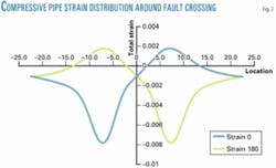
Using nonlinear force-displacement curves for the pipe-soil interaction in all three directions and stress-strain curve from Equation 5, the maximum compressive strain is calculated to be 0.78% (Fig. 2). The maximum compressive strain is slightly larger than the strain criterion of 0.73% from Equation 4 and additional countermeasure is needed.
Due to the space limitation, re-orientating the pipeline is not considered. Instead, loose sand as backfill (i.e., no compaction) is suggested so that the pipe-soil interaction forces are greatly reduced.
As a result, the maximum pipe strain is 0.56%. Since this reduced strain is below the criterion, seismic design of the pipeline at the fault crossing is achieved with loose sandy backfills.
Countermeasures
Pipeline design and upgrade at a fault crossing can be achieved by a number of means. The methodologies discussed previously are also applicable to verify the effectiveness of a chosen countermeasure.
For an existing pipeline, countermeasures for reducing soil restraints are recommended. These countermeasures include:
1. Loose backfills (e.g., loose sand).
2. Smooth coating (e.g. plastic sheet wrapper).
3. Casing technique (e.g., building a culvert).
4. Shallow burial (remove some of soil cover).
5. Unburial (remove all soil cover).
6. Wide trench and compressible or crushable material around the pipeline to accommodate lateral fault offset.
For a new pipeline project, the following methods can also be considered:
1. Choosing favorable orientation for a pipeline crossing an active fault before any countermeasures for reducing soil restraints are used.
The pipeline should be oriented such that the pipe strain due to a strike-slip fault movement is in tension.
For a reverse fault crossing, the intersection angle needs to be as small as possible to minimize the axial fault component and hence the maximum compressive strain in the pipe.
2. Avoiding large permanent ground-deformation zones in pipeline route selection if economically practical.
3. Using a large plastic casing pipe (e.g., corrugated plastic pipe).
4. Laying the pipeline on the ground or seabed.
5. Increasing wall thickness of the pipe.
6. Using high grade steel for the pipe.
7. Applying prestress to the pipe with a controlled tie-in temperature.
Which countermeasure should be used depends upon many factors such as costs, amount of potential fault movement, soil resistance and properties, site availability, and so forth.
When a fault movement is no more than a couple of meters, countermeasures can be chosen in the following priority order:
1. Considering favorable orientation.
2. Considering methods to reduce the pipe-soil interaction forces.
3. Considering pipe upgrade (increasing wall thickness, or using high grade steel).
For an onshore pipeline crossing very large fault movement (e.g., > 5 m) in compression, laying the pipeline aboveground on slippers is suggested if rerouting and reorientation are impractical.
Expansion loops or zig-zag configuration is required to accommodate axial and lateral fault deformations. The design of 48-in. TransAlaska Pipeline at the Denali fault crossing was a successful example of this kind in which the zig-zag configuration is used along with H supports right next to the pipe segment on slippers.
Sliding mechanisms are also provided at the H supports partially to absorb the axial and lateral deformations.
The right strike-slip Denali fault displaced 4.3 m horizontally and 0.8 m vertically on Nov. 3, 2002, and put the pipeline in compression. The pipeline only suffered minor damage, however, such as supports tilted, pipe shoes displaced on slippers.
In the case that exact fault location is uncertain or it is impractical to achieve an acceptable design by the countermeasures mentioned above, remotely controlled block valves need to be installed at least 200 m from possible fault movement zone.
In this case, a risk-assessment analysis and repair plan needs to be ready, and related parts need to be stockpiled for this particular crossing. In the case that a sharp bend or a tee is needed, the bend or tee should be outside of the pipeline affected by the fault.
References
1. Kennedy, R., Chow, A., and Williamson, R., "Fault Movement Effects on Buried Oil Pipeline," Journal of the Transportation Engineering Division, ASCE, Vol. 103, No. TE5, May 1977, pp. 617-633.
2. O'Rourke, M., and Liu, X, Response of Buried Pipelines Subject to Earthquake Effects, Multidisciplinary Center for Earthquake Engineering Research, 1999.
3. ASCE, Guidelines for the Seismic Design of Oil and Gas Pipeline Systems, 1984, Committee on Gas and Liquid Fuel Lifeline.
4. Hall, E., and Newmark, N., "Seismic Design Criteria for Pipelines and Facilities," Current State of Knowledge of Lifeline Earthquake Engineering, New York: ASCE, 1977; pp. 18-34.
5. Ramberg, W., and Osgood, W., "Description of Stress-Strain Curves by Three Parameters," Technical Note, No. 902 (1943), National Advisory Committee for Aeronautics.
6. O'Rourke, M., Liu, X., and Flores-Berrones, R., "Steel Pipe Wrinkling Due to Longitudinal Permanent Ground Deformation," Journal of Transportation Engineering, ASCE, Vol. 121, No. 5, September/October 1995, pp. 443-451.
7. ASCE, Guidelines for the Design of Buried Steel Pipe, 2001, American Lifelines Alliance.
The author
Jack X. Liu ([email protected]) is vice-president of Max Universal Inc., Houston, and has been a staff engineer of R.J. Brown Deepwater (Technip Affiliates). He has 15 years of research and design experience in both offshore and onshore pipelines. Liu holds a BS from Huazhong University of Science & Technology, Wuhan, China, and a PhD from Rensselaer Polytechnic Institute, Troy, NY. He is a registered professional engineer in Texas.


