Reservoir characterization improves stimulation, completion practices
BARNETT SHALE— Conclusion
Improved reservoir-characterization insights allow operators to custom-fit stimulations and completion practices in the highly variable Barnett shale reservoirs.
This concluding article in a two-part series that began in OGJ, Jan. 19, 2004, p. 51, on the Barnett shale covers the current practices of stimulating and completing the Barnett shale wells in the Fort Worth basin of Texas.
Waterfracs open play
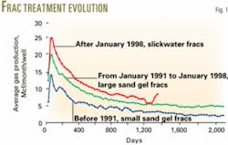
The initial stimulations in the Barnett shale play were small, conventional, 500,000-lb sand gel fracture treatments that soon gave way to large, conventional, greater than 1.5-million-lb sand gel fracs.
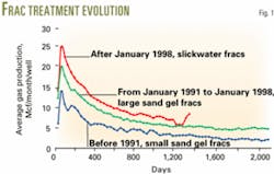
Growth in the play, however, did not escalate until the mid-1990s with the design and application of a more economical fracing solution, slickwater fracs or waterfracs. These types of fracs could achieve production results equal to or better than the conventional approaches (Fig. 1).
Waterfracs involve pumping large volumes, ±1 million gal, of lightly treated fresh water filled with low sand concentrations, ±100,000 lb of sand, at high pump rates. These treatments result in higher initial production rates because they extend the fracture length in the low-permeability Barnett shale, thereby connecting more reservoir rock to the wellbore.
Traditional methods for achieving good fracture extension require pumping large volumes of propping agents carried in viscous, gelled fluid systems. Waterfracs reduce the need for both the propping agent and carrying fluids, arriving at an equally effective yet less expensive (more than 50% cost savings/ well) and less viscous fracturing system.
Operators have applied further improvements in well stimulations and completions designs as they have gained more reservoir characterization insights to custom-fit stimulations to the highly variable reservoirs found across the play.
Current stimulation goals
Barnett shale operators currently focus on three primary stimulation objectives. Stimulations that deliver maximum frac-face exposure remain a priority; however, this objective is tempered with both the desire to have all Barnett pay zones flowing into the wellbore and the requirement to avoid surrounding water-bearing zones.
Barnett shale zones have an average permeability less than 0.001 md; therefore, a very large reservoir surface area must be connected to the wellbore in order to have sufficient hydrocarbons flowing into the wellbore. Modeling has revealed that each hydraulically created fracture and existing natural fractures drains a small surrounding area.
These wells need some near-wellbore conductivity to have good well clean-up, specifically adequate flowback of the load fluid. Otherwise the frac water remains trapped in the reservoir, impeding hydrocarbon production.
Another consideration is that the well needs to flow from as many Barnett pay zones as possible after the initial stimulation because the produced gas will have to lift the load fluid to the surface. At lower gas rates, the well may need artificial lift, at an added cost, for lifting the load water that is migrating back into the wellbore.
In addition to load fluid impacting the production, water from surrounding reservoirs can impede production unless stimulations avoid these zones. Electrical images can help identify water zones that must be avoided.
Existing faults, because they are the path of least resistance, can divert the frac fluid, thus minimizing the impact of a stimulation treatment by reducing the amount of or completely preventing reservoir rock from being cracked and connected to the wellbore.
Faults are another possible source for water flowing into the wellbore. Operators have employed 3D seismic to help them avoid existing faults. In this case, they select drilling locations away from fault planes to minimize the fault's impact on production.
Need for stimulation staging
Dipole sonic and standard logs form a starting point for a Barnett shale stimulation design. Rock stresses and other rock properties that affect how easily a given zone will fracture guide design decisions. Changes in stresses, a large gross pay interval (complete Barnett section), and variations in rock strength will require a change in a well's completion design.
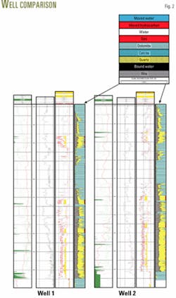
Fig. 2 shows a comparison between two neighboring wells with almost identical feet of pay and logging responses. Well 1 is about 0.5 miles east of Well 2. The gross Barnett interval in each well is more than 750 ft thick and has nonproducing rock lying between the gas producing reservoir sections.
As previously stated, operators now know that for maximum economic return, it is critical for Barnett shale wells to have all reservoir pay stimulated and flowing into the wellbore after the initial hydraulic stimulation. When the reservoir sections are not stacked directly on top of each other, as seen in the original Barnett play areas within Wise and Denton counties, it may become necessary to design more than one stimulation stage for the Lower Barnett zones.
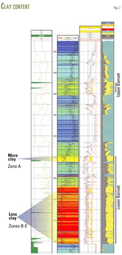
For example, as shown in Fig. 3, the Lower Barnett shale Zone A in Well 2 had an average stress gradient of 0.1 psi/ft greater than Zones B through E. A hydraulic fracture stimulation model indicated that Zone A would not break down when treated with the rest of the Lower Barnett. Use of dipole sonic measurement along with the other log measurements determined this variation in stress gradient.
In contrast, dipole sonic measurements were unavailable prior to Well 1 being stimulated, and the assumption was made that stresses in the Lower Barnett did not vary significantly.
After completing the nearby Well 2 and taking production logs in Well 1, the operator found this stress assumption was incorrect.
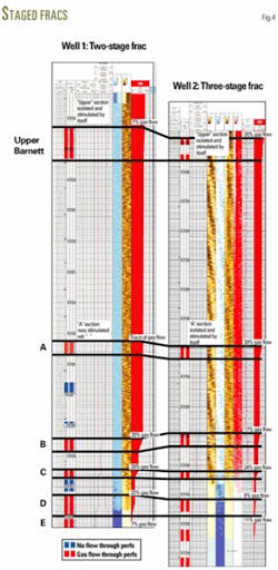
Analysis of the production results from these two wells (Fig. 4) indicates that it appears that Well 1, Zone A, went unfraced, because it is not contributing significant production in comparison to the same zone in Well 2.
Production logs (spinner, gradiometer, and bubble counter) showed a flow profile of each well. In Well 1, Zone A, contributed only a trace of gas, while Zone A in Well 2 provides 20% of total gas flow.
In fact, Well 1 underwent a two-stage stimulation, and stimulating the lower section in bulk did not provide enough incremental pressure change to overcome the higher stresses in Zone A.
Well 2, however, underwent a three-stage stimulation, including the isolated stimulation of Zone A at a higher stress gradient.
Refined perforation placement
In addition to designing the optimum number of stimulation stages based on local Barnett shale conditions, the design team must consider perforation placement. For such wells as shown in Figs. 2-4, the perforations should be placed in the zones that are easiest to break.
These are zones with lower clay content or natural fracturing already present. In these cases, the resulting frac will have the maximum areal extent and more migration pathways for the hydrocarbons.
In the case of Well 1 (Fig. 4), no frac fluid flowed through several sets of perforations. Instead, the frac fluid took the path of least resistance and only entered those perforations with the easiest rock to break. The frac may have left the rock behind the untouched perforations unstimulated, or it may have stimulated the rock from nearby perforation sets that are above or below the untouched perforations.
In the latter case, the hydrocarbons likely would migrate through long and tortuous pathways that would impede flow. If completely unstimulated, the unpropped fractures could close, leaving potential production untapped.
A comparison of perforation placement on Well 1 (Fig. 4) with its type log, Fig. 2, shows that the perforations are in zones with high clay volumes and no fractures. Electrical images or seismic can identify the presence or absence of fractures.
Well 2, on the other hand, had perforations placed only in cleaner zones with low clay content that includes natural fracturing. This is in addition to adding the third stimulation stage to isolate Zone A.
The approach in Well 2 resulted in all perforation sets flowing gas for maximum production.
Water production, load water flowback
After completion, Barnett shale wells will produce water that stands at the bottom of the wellbore. The logs (Fig. 4) show the water as a solid blue band at the bottom of Tracks 4 and 5 in Wells 1 and 2, respectively.
Standing water chokes gas flow from any perforations alongside it because gas must trickle through the water before it comes to the surface. Clearly, operators must eliminate a standing water column to maximize production.
In some cases, a well will load up with water so that initiating flow requires swabbing or pumping it out. Water production problems often occur more than once in a well.
Load water flowback volumes after a stimulation treatment vary well to well, depending upon the type of hydrocarbons present and the complexity of the fracture treatment. Load recoveries may be as low as 20-30% or as high as 60-90%.
Dry-gas wells typically have the least fluid recovery, while oil wells have the most. When load recoveries approach the higher percentages, it is possible that the treatment connected the reservoir to a water source. A measurement of the total solids in the recovered water is an easy check for determining the source of the water.
Advanced imaging, drilling practices
During the last few years, operators have applied an interesting real-time technique for precisely tracking the areal extent and direction of some Barnett shale stimulation treatments. The Barnett play generally has a northeast-southwest trending natural fracture system but local variability does exist, and play development must take into account the depleted zones in the more densely drilled regions.
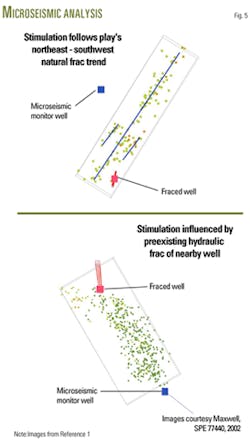
In Fig. 5, the microseismic images of the fracturing treatment placed in the top well show that the stimulation was effective mainly to the northeast and along three parallel lines that follow the predominant fracturing trend.
Meanwhile, the images taken of the bottom well treatment found that it flowed into the preexisting fracture system created for a nearby well. The treatment essentially was lost into an already depleted reservoir area. Reference 1 provides more detail about microseismic techniques.
As the Barnett shale play continues to expand, within infill as well as stepout and exploratory wells, operators must consider potential interference between wells. Techniques such as microseismic imaging hold promise for providing the precise details about reservoir dynamics that will be required to effectively manage a maturing play.
Horizontal wellbores also have emerged during the last few years as a technique of interest in the Barnett shale play. A plus for the horizontal technique is that it can more precisely tap new reservoir areas while avoiding depleted or water-filled zones. Also important is that these wellbores can increase possible initial production because they have more areal extent in this tight formation.
Also, as the Barnett play extends into some highly urban areas, horizontal wellbores provide the extended reach needed to produce from untouched portions of the play.
Reference
1. Maxwell, S.C., et al., "Microseismic Imaging of Hydraulic Fracture Complexity in the Barnett Shale," SPE Annual Technical Conference and Exhibition, San Antonio, Sept. 29-Oct. 2, 2002.
