Hydrocyclone study enables GOSP debottlenecking
Vilas S. Koleshwar
Mohammed A. Al Sahli
Saudi Arabian Oil Co.
Dhahran
This article describes Saudi Aramco's efforts in confirming the adaptability of hydrocyclone technologies in debottlenecking a gas-oil separation plant (GOSP). It also presents the comparative performance results obtained during the field tests of two different innovative hydrocyclone technologies.
The site for the technology field tests was the world's largest onshore GOSP, in northern Saudi Arabia, that processes Arabian Heavy and Arabian Medium crudes from offshore production platforms.
Driven by an increase in water cuts and formation of tighter emulsions from some sections of the oil field, the GOSP needed debottlenecking in both oil processing and produced-water treatment (PWT) sections. On top of this, the likelihood of using tighter formations for future produced-water disposal necessitated stringent oil-in-water (OIW) specifications for disposal water quality. The new OIW target specification-20 mg/l. (max.) for disposal water quality-called for a thorough review of the existing produced-water treatment system.
Finalizing technology options is a staged process in Saudi Aramco, starting with screening of new PWT technologies, followed by economic evaluation, and then confirmation of operational performance through online pilot tests of the technology prototypes.
For augmenting the existing produced-water treatment plant (corrugated plate interceptors), secondary PWT technologies, such as liquid-liquid hydrocyclones (conventional tangential flow, mixed flow and axial flow), were screened and subjected to Saudi Aramco's technology validation process. This was in addition to the augmentation of pumping capacities for handling increased produced-water rates.
Compact and state-of-the-art technologies were preferred during technology screening because they would be easy to build and operate during commercial implementation at the existing site.
Largest GOSP
The largest onshore Saudi Aramco GOSP in the northern area is designed to process Arabian Heavy (AH) and Arabian Medium (AM) from several offshore platforms to produce export-quality crude oil, pipeline-quality natural gas, and injectable-quality produced water.
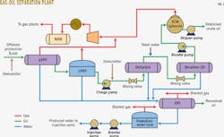
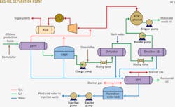
Fig. 1 shows a schematic of the plant.
Production from offshore oil wells flows to three-phase low pressure production traps (LPPTs) and low-pressure degassing tanks (LPDTs) to separate oil, gas, and water. Oil field chemicals added in the production fluids include demulsifiers and corrosion and scale inhibitors.
The gas is gathered, compressed, and transferred to the gas plant for further processing. The wet oil flows to LPDTs for bulk water separation. Wet oil with the remaining emulsified water flows to the dehydrators and desalters, where it is washed with less-saline wash water to remove the emulsified water from wet oil and produce dry oil having <0.2% bs&w and 10 lb/1,000 bbl salt. The dry crude product is then transferred to pipelines or shipped for end users.
Produced water separated in LPPTs, LPDTs, dehydrators, and desalters is sent to corrugated plate interceptors (CPIs), where the water is treated to separate oil and produce injection-quality water. The treated produced water moves to the formation-water storage tank and on to disposal wells via booster and injection pumps, in conformance to stringent environmental regulations.
Water disposal
The CPIs were designed to treat produced water having OIW of 1,000-2,000 mg/l. down to the target disposal water specification of 50 mg/l. As water cuts in produced fluids from oil fields increased, the tighter oil-water emulsions started forming, which resulted in a higher dose of demulsifier chemical to achieve the desired crude quality. It was observed that the treated produced-water quality for disposal exceeded the target OIW limit more often, resulting in higher back-pressure from disposal wells. Actual disposal-water quality ranged 50-100 mg/l., with occasional OIW excursions to >100 mg/l.
As the GOSP processes AH and AM crudes from offshore wells, the formation of tight oil-in-water emulsions, especially during winter, is a main cause of the off-spec quality disposal water. This is besides the fact that the oil-water emulsions are caused by the inherent oil-water chemistry, as well as external chemical additions for oil processing.
An oil-producing reservoir associated with this GOSP has sufficient aquifer pressure and therefore does not need water injection for reservoir pressure maintenance. As a result, the produced water has to be disposed of in the water-disposal formations for environmental reasons.
Saudi Aramco has identified a few such water-disposal formations with varying depths, permeability, and porosity. Currently, although the disposal formation with higher permeability and porosity has been used, it is likely that a switch to deeper and tighter formations will be required when disposal capacity of the current disposal formation is reached. As the water cuts in production fluids speed up, such a limit is likely to be reached sooner.
During injection of produced water into tight formations, high OIW contributes to a significant loss of water injectivity. As a consequence, maintaining the injection wells becomes more expensive. Usually, these wells are plugged more often when OIW content in disposal water exceeds the target OIW specification.
To restore well injectivity, well clean-up jobs are frequently performed and in some cases additional wells are drilled when it is found that the injectivity cannot be restored. To optimize drilling costs for additional disposal wells, planners considered low OIW content in the disposal water to address the low injectivity of tighter formations.
Produced-water disposal quantity and quality has therefore become a major concern for sustaining oil production capacity from this GOSP. Consequently, Saudi Aramco has recognized that the presence of oil-in-water can make it less desirable to inject produced water into disposal or injection wells. Therefore, a more stringent environmental limit was proposed by Saudi Aramco (i.e., 20 mg/l. or lower), making it important to find effective produced-water treatment systems able to comply with these regulations.
New solution
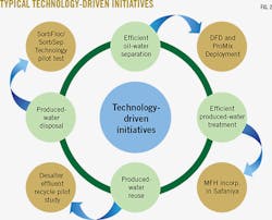
Saudi Aramco has addressed increasing produced-water rates with action on four fronts: oil-water separation, efficient produced-water treatment, produced-water reuse, and produced-water disposal. Fig. 2 illustrates each solution.
To prepare for the increased rate and stringent quality of disposal water set by Saudi Aramco, engineers initiated a new technology screening process that identified liquid-liquid hydrocyclone technologies for the future.
The mixed flow hydrocyclone (MFH) and axial flow hydrocyclone (AFH) were identified as potential secondary produced-water treatment technologies.
The next step in this process involved online field tests of these technology prototypes.
The objective of such a test was to confirm if the technology could perform with actual feed stream from the GOSP and handle varying oil excursions and still achieve the disposal water quality of ~20 mg/l. OIW from the feed stream containing >100 mg/l. OIW while maximizing oil recovery and maintaining high injectivity.
An economic evaluation based on commercial-scale installation of a hydrocyclone technology unit was also performed to estimate the rate of return and payback period, using the budgetary capital expenditures and operating expenditures for the new equipment.
When hydrocyclone technology is deployed for addressing water disposal issues, we can anticipate the following advantages:
• Low maintenance due to no moving parts in hydrocyclones.
• Smaller footprint for additional equipment.
• Higher separation and recovery of suspended hydrocarbons with smaller particle sizes.
• Lower disposal costs of disposing spent coalescing filter media.
• Oil separation and recovery without the need of chemicals or heat.
• Reduction in well clean-up jobs.
• Fewer disposal wells.
• Water disposal into tighter formations.
Hydrocyclone technologies
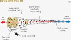
Fig. 3 shows a typical hydrocyclone.
The feed enters the cyclone tangentially under pressure through an inlet in the top of the cylindrical chamber. As the feed enters the chamber, the rotation of the liquids inside the cyclone begins, causing centrifugal forces to accelerate the movement of heavier phase (water) toward the outer wall. The heavier phase, after reaching the wall, traverses downward in a spiral pattern through the cylindrical section and into the conical section.
At this point, the lighter phase (oil) migrates toward the lower pressure central core, where an axial reversal of flow occurs, resulting in the lower density oil's enriched phase spiraling upwards and out through the small-diameter orifice (the reject port or the vortex finder) in the center of the inlet head. The oil-depleted heavier phase remains in a downward spiral path along the walls of the conical sections and gradually exits through the tip of the tail pipe.
The lighter phase, being compelled to occupy the thinner central core, leads to coalescence of smaller oil droplets to larger ones. The stream leaving the small-diameter port is called "reject" or "overflow," and the stream leaving through the tail pipe is called "underflow."
Saudi Aramco screened and compared three hydrocyclone technologies: conventional or tangential flow hydrocyclone (TFH), mixed flow hydrocyclone (MFH), and axial flow hydrocyclone (AFH), out of which it selected MFH and AFH technologies for field testing.
The major difference among these hydrocyclone technologies is the swirl-generation technique built in the feed entry section of the hydrocyclone liner.
The feed entry section is designed to swirl the feed stream efficiently, so that it generates very high separation forces on the coexisting immiscible oil and water phases, causing the relative movement between higher-density phase (water) and lower-density phase (oil). The liquid in swirling motion traverses complex flow paths, subjecting the two liquid phases to three types of velocities: tangential, radial, and axial.
The relative movement of phases is subjected to three types of forces:
• Centrifugal: An inertial force on both the phases related to tangential velocity.
• Centripetal: A dragging force caused by radial movement of the two phases.
• Axial: A force caused by axially moving phases.
In a TFH, the feed enters the inlet section tangentially through one or two tangential inlet ports. In an MFH, the feed enters the inlet section tangentially perpendicular to the liner axis through multiple tangential entry ports. In an AFH, the feed enters the inlet section of the hydrocyclone liner longitudinally parallel to the liner axis, where it comes across a swirler device that directs the flow of fluid in a radial and circular direction, causing it to rotate in cyclonic motion.
MFH uses an innovative airfoil principle to set the flow in rotation, while the AFH uses the impact of the feed on the swirler blades and liner wall to cause the cyclonic motion. The TFH uses only the impact on the liner wall to cause the cyclonic motion inside the feed section of the hydrocyclone liner.
TFHs are often unable to meet the stringent OIW specifications, even though they have been present in the upstream produced-water market for a long time. This is mainly because produced water has been experiencing tight oil-water emulsions, requiring advanced and highly efficient phase-separation be built into the hydrocyclone design. A tight emulsion is formed with a median droplet size of <20µ. The required median particle size is >20µ.
MFHs and AFHs use an innovative swirl-generation method that is different from TFHs.
The mixed and axial flow swirl-generation method potentially prevents high velocities at the cyclone walls. High wall velocities lead to high friction at the wall, which in turn causes rapid swirl decay, high undesirable pressure drop, and increased flow turbulence. The mixed and axial flow swirl-generation principle, on the other hand, is likely to result in a lower pressure drop and a more stable central core.
The MFHs and AFHs are unique in that they reduce the negative effects usually encountered in conventional hydrocyclones, such as boundary layer disturbances and flow destabilization. This comparison is summarized as follows:
TFH disadvantages include:
• Asymmetric flow pattern; can cause re-entrainment of separated oil.
• Preferential flow path likely to cause severe erosion.
• Higher pressure drop due to inefficient energy conversion.
MFH and AFH advantages over TFH include:
• Higher separation efficiency.
• Lower pressure drop.
• Flow stabilization in the cyclone.
• Preseparation in the cyclone head.
• Cyclone heads being removable (for inspection and cleaning purpose).
Saudi Aramco selected AFH and MFH over the TFHs and considered them candidates for field tests to confirm their relative performance.
MFH field test
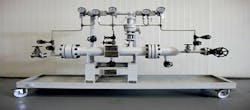
The MFH test skid was specially designed and fabricated to Saudi Aramco standards for the field test (Fig. 4):
• Design pressure: 245 psig.
• Design temperature: 110° C.
• Design code: ASME §1, Div. VIII.
• Capacity: 10 cu m/hr.
• Fluid handled: oily water with a salinity of 200,000 mg/l.
• Materials of construction: super duplex stainless.
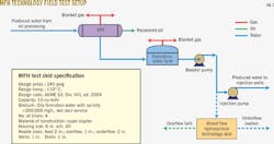
Fig. 5 shows how the MFH test skid is connected to the existing plant. The feed to the skid comes from the discharge of the existing booster pump. The overflow and underflow lines from the skid are connected to the booster pump's suction piping.
Installation of the MFH skid was completed on Nov. 22, 2010, and the pilot test started on Nov. 23, 2010. The feed rate varied from 6-12 cu m/hr in steps of 1 cu m/hr by adjustments to the underflow differential pressure. The overflow/reject portion was adjusted 2%, 3%, 4%, 5%, and 6%, by varying overflow differential pressure.
After the first test, the MFH unit was kept operating for a week, and a second test was conducted on Nov. 30, 2010. The reason for the second test was to confirm if any performance degradation had occurred over a week's MFH operation.
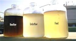
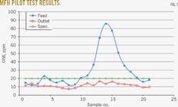
Fig. 6 shows the samples collected during the pilot test from feed, underflow, and overflow pipes of the MFH skid. Fig. 7 shows the laboratory analysis results.
Table 1 summarizes the overall performance of the MFH over the 2 days of pilot tests. Analysis confirmed that the MFH technology can achieve < 20 mg/l. OIW, regardless of occasional oil excursions in the inlet feed stream.
AFH field test
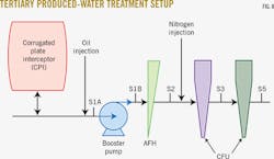
AFH technology was tested at the same GOSP as a part of the tertiary produced-water treatment technology test program May 28-June 15, 2012. For a conservative approach, Saudi Aramco obtained the produced-water feed from the inlet to the existing CPI. The test equipment in this technology test consisted of a booster pump, AFH, and compact flotation unit with flocculent injection unit. Fig. 8 shows how these components were interconnected.
The test samples were analyzed in Saudi Aramco's laboratory. The full test system was used during this test program. For individual equipment performance, AFH and compact flotaation unit were bypassed. Evaluating performance at higher oil concentrations involved injecting oil at the inlet of booster pump.
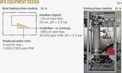
The chosen operating conditions facilitated comparison with the expected produced-water problems at the offshore facilities. Water temperature and inlet oil concentration are especially important for proper comparison. Fig. 9 shows the design details of AFH equipment.
Separation by hydrocyclone strongly depends on droplet size; smaller droplets usually mean worse separation. The inlet droplet size was negatively influenced by the centrifugal booster pump upstream of the hydrocyclone separator. The separating conditions are therefore considered difficult. No chemicals were injected upstream of the hydrocyclone.
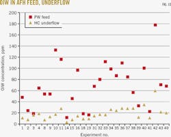
During the test, oil concentrations in water from the CPI fluctuated between 11.4 and 180 mg/l. The hydrocyclones were able to reduce the oil concentration to 2-59 mg/l. with an average efficiency of 70%. Fig. 10 shows the feed and residual oil concentration in the underflow of the hydrocyclone.
Table 2 shows that oil-removal efficiency increases with higher inlet-oil concentrations, although the higher efficiency cannot prevent an overall higher oil concentration at the outlet of the hydrocyclone stage.
Analysis of results in Table 2 confirmed that the AFH technology can achieve <20 mg/l. OIW, if the oil excursions in the inlet feed stream are not excessive (>100 mg/l.).Benefits; design
A significant annual cost savings can be realized with implementation of MFH/AFH technology at the GOSP by way of reducing clean up jobs, drilling fewer disposal wells, and reducing maintenance and energy costs. Implementation will also enable disposal of water into tighter formations.
The following elements should be considered in the design of MFH/AFH technologies for produced-water treatment:
• Oil droplet size distribution should be included in design input.
• Presence of solids and gas in produced water should be identified before design. The solids and gases are known to plug the reject orifices and cause erosion of the hydrocyclone liners.
• Low-shear feed water pump and inlet piping is preferable. The potential of a reject-stream pump also exists.
Analysis and results of the MFH and AFH technology pilot tests yielded the following conclusions:
• Both MFH and AFH technologies produce desired de-oiling performance and stable operation, in spite of wide variations in feed compositions and flow rates.
• The MFH and AFH technology pilot tests demonstrated an acceptable range of separation efficiencies, confirming that they are suitable for debottlenecking the existing gravity-based produced-water treatment as secondary produced-water treatment to achieve the desired disposal water quality of <20 mg/l.
Acknowledgments
The authors thank Saudi Aramco management for allowing them time and resources to develop and publish this article.
Bibliography
Albluwi, Saif, "Debottlenecking of Produced Water Treatment Facility in Mature Heavy Oil Fields," SPE Applied Technology Workshop, Mar. 20-21, 2012, Al-Khobar, Saudi Arabia.
Gomez, Carlos, Caldentey, Juan, and Wang, Shoubo, Gomez, Luis, Mohan, Ram, and Shoham, Ovadia, "Oil/Water Separation in Liquid/Liquid Hydrocyclones (LLHC): Part 1-Experimental Investigation," SPE Annual Technical Conference and Exhibition, New Orleans, Sept. 30-Oct. 3, 2001.
Meldrum, N., "Hydrocyclones: A Solution to Produced Water Treatment," Offshore Technology Conference, Houston, Apr. 27-30, 1987.
Koleshwar, Vilas S., and Albluwi, Saif F., Saudi Aramco internal document SAER-S6431-12, final report on SorbFloc/SorbSep technology test at Safaniyah onshore GOSP, 2012.
Koleshwar, Vilas S., and Mulhim, Ahmad A., "Debottlenecking of Produced Water Treatment Facility in Mature Heavy Oil Fields," SPE Global Integrated Workshop Series, Nov. 5-7, 2012, Muscat, Oman.
Koleshwar, Vilas S., and Al-Yousef, Khaled A., Saudi Aramco internal document SAER-S6306-11, final report on mixed flow hydrocyclone technology test at Safaniyah onshore GOSP, 2011.
Koleshwar, Vilas S., Al-Yousef, Khaled A., Schook, R., Abu El-Rub, Z., and Lamers, Bart, "A Field Trial and CFD simulation of Produced Water Treatment using Mixed Flow Hydrocyclone," Offshore Technology Conference, Apr. 30-May 3, 2012, Houston.
The authors
Vilas S. Koleshwar ([email protected]) is an engineering specialist in the process and control systems department in Saudi Aramco. He specializes in oil and water treatment and has more than 26 years of professional experience in the oil and gas industry (conventional and unconventional) in India, Kuwait, Canada, and Saudi Arabia. He also spent 6 years in project and operations in ethanol based the chemical industry in India. He holds a BTech in chemical engineering from the Indian Institute of Technology, Kharagpur, and professional engineer membership with APEGA, Canada.
Mohammed A. Al Sahli ([email protected]) is an engineering supervisor in the process and control systems department in Saudi Aramco. He has more than 19 years of technical and management experience in crude oil production and processing. He holds a masters in chemical engineering from Carnegie Mellon University, Pittsburgh, Penn., and a bachelors in chemical engineering from King Fahd University of Petroleum & Minerals.
