Employing liner drilling technology can mitigate deepwater wellbore instability
Steven M. Rosenberg
Deepak M. Gala
Weatherford International Ltd.
Houston
While deepwater drilling presents a myriad of challenges, perhaps one of the most economically and technically taxing relates to the risk of lost circulation. This phenomenon, in which whole drilling mud enters the formation from the wellbore, introduces several setbacks, ranging from the loss of thousands of barrels of expensive drilling mud to the irreversible collapse of the wellbore.
There are a number of technical solutions to prevent this, and liner drilling technology is one of the most viable candidates. Drilling-with-liner alleviates several wellbore instability concerns, including minimizing lost circulation. The technique also introduces a narrow annular geometry, which reduces the rate of fluid loss in the annulus and enables effective management of the annular fluid level, as contrasted to conventional drilling operations. Liner drilling has been shown to minimize or eliminate nonproductive time in operations in which uncontrolled fluid losses have been encountered previously.
Weatherford has developed a suite of liner drilling technologies designed to mitigate instability issues and address the challenges of drilling through narrow mud weight/pore pressure/fracture gradient windows that conventional methods cannot.
Deepwater case history
A deepwater Gulf of Mexico operator availed of liner drilling technologies to develop updip reserves in a deep, depleted gas reservoir located in 2,900 ft of water.
The planned well was a replacement for a well that had produced from a deep sand interval below 18,000 ft true vertical depth (TVD). This sand interval was drawn down 5,000 psi to an estimated 8.0 ppge (equivalent) pore pressure, while virgin shales and wet sands above the pay had pore pressures of 13.7 to 14.4 ppge compared with the 10.5-11.5 ppge fracture gradient that was anticipated in the target sand.
A shallower pay interval at 15,000 ft TVD dictated the need for a high casing seat and an S-shaped wellbore with a 5,000 ft long section at a 60° inclination and a departure from vertical of some 5,000 ft in order to access the deeper depleted sand at the planned location.
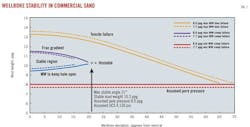
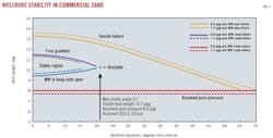
The main challenge for the operator was to drill and set casing through a normally pressured shale and a depleted sand within one hole section towards its end (Fig. 1). Achieving this with conventional methods would most likely require two strings of casing, with increased risk of failing to reach the target depth.
The well plan would not allow for an additional string to be utilized due to severe slimming of the wellbore. The operator created a multidiscipline operations team to prepare procedures for drilling in a 75⁄8-in. liner through unstable shale formation, while also mitigating any potential hole instability and depletion issues. A review of drilling reports from the original producing well showed that two sidetracks were required to successfully install the 75⁄8-in. production liner completion assembly as hole instability was an ongoing problem.
Subsequent wellbore analysis led to the conclusion that the depleted commercial sand section would be unstable at hole inclinations exceeding 22°. Higher inclinations would make wellbore stability a challenge, and would require incrementally higher mud weights and increase the probability of severe lost circulation.
Rock mechanics analysis predicted that the wellbore through the sand zone would be unstable at deviations greater than 50° and that the mud weight would have to be sufficient to keep the wellbore open by offsetting the weight of the overburden acting to close the well. Mud weight has to increase with increasing deviation, but if the mud weight exceeds the fracture gradient, lost circulation would occur.
Conversely, a mud weight that is too low would cause wellbore collapse. This same wellbore analysis also concluded that shale failure would occur at mud weights less than 12.5 ppg and that a main objective should be to reduce the amount of shale exposed by keeping the hole close to vertical in that section. The mud weight required would vary from 13 ppg at 22° to 13.7 ppg at 60°.
To avoid mud losses the nominal mud weight while drilling the target sand would need to be 10.3 ppg with very little drilling window margin of error being available. The wellbore analysis indicated that a mud weight of 9.6 ppg may be preferable to provide headroom for the equivalent circulating density (ECD) that would exist while drilling.
The drilling plan
After a full review, the operations team decided that a 75⁄8-in. liner would be drilled into the pressured shale formation and set and cemented just above the depleted sand target zone. To minimize the shale section exposed, which would theoretically close in with 10 ppg mud, a 51⁄2-in. liner would be drilled into the target sand itself and cemented in place.
Several features of liner drilling were considered beneficial to this operation. First, liner drilling had a successful track record of minimizing or even eliminating lost circulation problems due to the so-called "smear effect." This effect is believed to occur due to the close proximity of the casing to the wellbore, resulting in cuttings being smeared against the formation to create an impermeable mud cake. In regular drilling operations the greater space between the drill pipe and the wellbore does not promote this.
This same reduction in annular space also leads to much higher annular velocities for the same flow rate, leading to better hole cleaning—an important benefit in unstable shale formations. Once liner setting depth is reached, cementation can occur almost immediately, further reducing the need for hole cleaning that is typically associated with standard drilling operations before casing is set. This can result in significant rig time savings and remove the risks associated with tripping the drill pipe.
Because the liner drilling operation was to be carried out in a water depth of 2,900 ft, additional factors had to be included in the drilling plan. Operational procedures were written to highlight the differences between liner drilling and conventional drilling operations in deep water, and training sessions were held for key drilling personnel, service engineers, and third parties to ensure that these differences were fully understood.
The liner was fitted with rigid body, spiral blade centralizers to reduce the potential for differential sticking.
In addition, contingency plans were prepared in the event of fluid losses during liner drilling, as the preset shear pin pressures for the hydraulic liner system hanger and running tools were sensitive to differential pressures between the inside of the liner sting string and the annulus.
With partial fluid losses, if the annulus could be kept full, drilling ahead could continue. If the annular fluid level could not be managed, the liner would be cemented in place immediately. In the event of fluid losses both inside the liner and in the annulus, the liner would be set and cemented immediately so that the well could be secured.
Equipment selection
To select suitable equipment for the proposed project, consideration had to be given to torque and drag probabilities, liner connection torsional strength, cyclic fatigue resistance, drilling fluid hydraulics, and surge concerns while running the liner in the well.
The following equipment was selected for the 75⁄8-in. drilling liner:
• A 75⁄8-in., 39 ppf, Q-125, HYD 523 liner was chosen following mechanical and fatigue analysis of estimated liner drilling loads based on 20,000 lb weight on bit (WOB), 100 RPM for 150 hr, and 60° hole inclination.
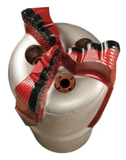
• A three-bladed, 75⁄8 in. by 81⁄2 in. casing-while-drilling (CwD) bit incorporating PDC cutters on the shoulder was chosen for the application (Fig. 2). This bit contains an aluminum nose housing the three blades and three interchangeable 18⁄32-in. copper nozzles for hydraulics optimization. The CwD bit is drillable with conventional PDC bits as well as tricone bits, eliminating a dedicated bit and trip for drill out.
• Two double poppet valve high-temperature/high-pressure (HTHP) 75⁄8-in. float collars were placed 44 ft and 93 ft, respectively, above the CwD bit. The float collars provided a mechanical barrier for well control, as in a drill pipe float valve, and a one-way check system to prevent the cement to U-tube after the primary cement job.
• Two 75⁄8 in. by 81⁄4 in. blade OD centralizer subs were placed 22 ft and 46 ft, respectively, above the CwD bit.
• A 75⁄8 in. by 97⁄8 in. premium liner hanger system with a mechanically set liner top packer and a hydraulically locked, mechanically released liner setting tool, all capable of withstanding the calculated extremes of force that were used in the verification of the choice of liner connection.
Similar equipment was chosen for the 51⁄2-in. production liner but sized appropriately for the smaller liner.
Drilling the well
After setting casing strings and setting the 117⁄8-in. liner at 11,100 ft measured depth (MD), the liner shoe was drilled out and the hole kicked off, building angle at the rate of 3.5°/100 ft until an inclination of 59° was reached at a depth of 15,000 ft MD. The remaining 105⁄8 in. by 121⁄4 in. hole was drilled to 16,550 ft MD while maintaining this hole inclination.
Logging and evaluation were then performed, followed by setting 97⁄8-in. intermediate casing at 16,300 ft MD. An 81⁄2-in. hole section was drilled with synthetic oil base mud (SBM) to 20,455 ft MD when the rotary steerable system's bottomhole assembly (BHA) failed. Subsequently, the BHA failed twice and the hole packed off, resulting in the loss of the hole and the well having to be plugged back.
Bypass No. 1 was then drilled to a depth of 20,356 ft MD (18,053 ft TVD) using the 14.5 ppg synthetic base mud weight required for hole stability through the pressured shale formation, while maintaining a 50° inclination. The inclination was dropped to 20° to facilitate drilling of the depleted sand at the recommended angle. The target sand was encountered some 37 ft higher than expected and total fluid loss resulted while drilling with the 14.5 ppg SBM.
As a result, the annulus quickly packed off with the annulus fluid level remaining full, resulting in loss of the BHA. The drillstring was recovered and a second 81⁄2 in. by 97⁄8 in. bypass hole was drilled to 20,419 ft MD (18,040 ft TVD) and to a depth 13 ft TVD above the Bypass No. 1 TVD of 18,053 ft. The inclination at that depth was reduced to 20° to facilitate eventual drilling into the target depleted sand at the recommended angle.
The drillstring was then pulled after circulating to condition the well and 4,536 ft of 75⁄8 in. by 97⁄8 in. liner—complete with the CwD bit, liner hanger, packer, and setting tool—was tripped in the well at 9.7 fpm (9.4 min/stand) on the 51⁄2-in., 24.7 ppf, S-135, XT-57 drill pipe running string to a depth of 20,320 ft MD. The slow trip speed was required to minimize fluid losses to the exposed formations.
The 75⁄8-in. liner was then washed and reamed a total of 99 ft to TD and drilled a further 8 ft to 20,427 ft MD (18,049 ft TVD), some 15 ft above the top of the depleted commercial sand. Lost returns were encountered, with the annulus and liner running string remaining full.
The rotary stalled, and a decision was made to not work the pipe as the liner was at a sufficient depth to isolate the pressured shale and depleted interval. This enabled the mud weight in the subsequent hole section to be reduced to the 10 ppg required to drill the depleted commercial sand. The liner running string and annulus remained full. The 75⁄8-in. liner washing, reaming, and drilling process over the 107-ft interval took 31⁄2 hr to complete.
The liner hanger and packer were set and the liner cemented in place without incident. Following the prescribed period of waiting on cement, the float equipment, cement and CwD bit were drilled out with 12.7 ppg SBM and 5 ft of new 61⁄2-in. hole was drilled while reducing the mud weight to 10 ppg. The target zone was drilled using a 61⁄2 in. by 71⁄2 in. bicenter bit, maintaining the established inclination of 20° to 20,527 ft MD with full returns.
After conditioning the hole, the drill pipe and 61⁄2 in. by 71⁄2 in. BHA were retrieved and 328 ft of 51⁄2 in. by 75⁄8 in. production liner with 5½ in. by 61⁄2 in. CwD bit, liner hanger, packer, and running tool were run in. Weight on bit was required at 20,427 ft MD, from which point the liner was washed and reamed 100 ft to 20,527 ft MD (18,140 ft TVD).
The 51⁄2-in. liner washing and reaming process consumed 81⁄2 hr without fluid losses. The 51⁄2 in. by 75⁄8 in. liner was subsequently cemented in place without fluid losses, and the well was completed as planned.
Results and recommendations
The use of liner drilling technology greatly reduced the fluid losses in the annulus compared with conventional drilling methods deployed, most likely due to a combination of the "smear effect" and the reduced annular clearance that resulted.
Despite the difficulties encountered, which resulted in the loss of two hole sections due to the BHA failures, the target depth was reached successfully. Both liners were drilled and reamed in as planned. Given the hole conditions encountered, the operator concluded that the well could not have been completed without the use of liner drilling technology.
The operator and other service organizations involved in the project offered several recommendations on how to further improve liner drilling equipment and methodology.
To improve running and drilling hydraulics, the liner system needed to be redesigned to have more bypass area.
In addition, hydraulic liner hangers and setting tools need to have higher torque values to improve operations.
Rotation of pipe while making connections is advisable to facilitate the drilling of liners through thick depleted reservoirs and to lessen the probability of stuck pipe incidents.
Finally, a continuous circulating device is recommended when drilling through depleted intervals to allow for continuous pumping during the connection process.
The authors
Steve Rosenberg is US region product line manager for Weatherford's Drilling with Casing Group. He has over 25 years of experience in the oil and gas industry, previously holding drilling engineering positions with Diamond Offshore and Conoco. He has spent the past 8 years with Weatherford and manages its US and Gulf of Mexico drilling with casing operations. He has BS degrees in petroleum engineering from Mississippi State University and in biology from St. Lawrence University.
Deepak M. Gala is US commercial manager for all of Weatherford's products and services. He has over 8 years of experience in the oil and gas industry in the US and spent 1 year in the chemical industry in India. He holds a BS in chemical engineering from Mumbai University, an MS in natural gas engineering from Texas A&M University-Kingsville, and an MBA in finance from Tulane University.
More Oil & Gas Journal Current Issue Articles
More Oil & Gas Journal Archives Issue Articles
View Oil and Gas Articles on PennEnergy.com


