Pore pressure greatly affects drilling safety and the economics of drilling design and well construction.
This article focuses on how a calibrated 3D pore-pressure volume can be used to optimize well design when pore pressure and mud weight windows are the dominant issues in drilling.
Engineers often use estimated pore and fracture pressure profiles along the well path as primary input to the well design due to their overriding influence on casing seat selection. This, in turn, is the primary driver for hole geometry, casing program, and overall well cost. While this type of workflow has been used historically for wells in abnormally pressured areas, it also applies to wells drilled through depleted zones. More recently, this has also applied to deepwater wells, even when normally pressured, due to issues surrounding support of the mud column in the drilling riser.
High-quality 3D volumes of mechanical earth properties such as pore pressure and fracture gradient can provide detailed insight into relative pressure distributions within a volume. Reliable quantitative calibration, however, using data from drilled wells within the area, can deliver a more accurate pressure model in which to plan the well.
Integrating tools
Using 3D visualization with interactive well-path planning can provide more accurate modeling for drilling.
A typical well-planning workflow, based on a single 2D pore pressure and fracture-gradient prediction for the well, is forced to take the pressure profiles as fixed and build a casing and mud program around the constraints imposed by these profiles.
Integrating 3D pressure data with other appropriate tools allows the well-path trajectory to become an active variable in the well’s planning process. This can produce far more effective solutions than those constrained by fixed pressure profiles.
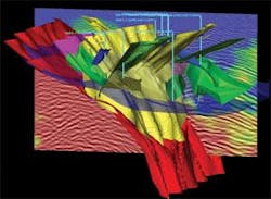
The first requirement to use 3D pressure data effectively for well planning is a visualization tool with the ability to corender multiple volumes and isolate features and data ranges through combinations of color and opacity. Fig. 1 shows 3D pore pressure values corendered with seismic data and existing wells in a structurally complex reservoir.
3D pore pressure values are corendered in color in this image, shown together with seismic data and existing wells in a structurally complex reservoir (Fig. 1).
A volume-based seismic interpretation solution is ideally suited for this requirement. Pressure sealing and nonsealing faults and formations can be more clearly distinguished, based on the presence or absence of pressure discontinuities across specific geologic boundaries.
Effectively planning a well in a 3D pressure volume requires a full-functioned well planning tool that can interactively create geometrically valid well paths in the 3D volume based on specified engineering constraints.
Using 3D visualization with interactive well path planning tools provides a powerful combination for optimizing the well-path pressure profile on a qualitative basis. For example, variable opacity displays can be used to identify visually areas where the pressure is above or below a certain gradient threshold. This can be effective in identifying routes to reach specific targets, avoiding isolated areas of abnormally high pressure. Furthermore, the ability to display volume data as ribbons and curtains along any well path allows visual determination of the pressure profiles in any given well.
Trajectory design alone, however, cannot determine how easily or even whether a well can be engineered and physically drilled.
Unified solution
The large number of interdependent variables involved in well design make it impossible to identify a single “best” design for any well. While it is often possible to optimize for a subject of the variables, it is unrealistic in almost all cases to determine the absolute optimal design covering all aspects of the well trajectory, casing program, drillstring, mud system, hydraulic, and rig requirements. Thus, there is a need to be able to iterate rapidly through many design options, to identify practical alternatives, and to focus engineering resources on the integrity of a chosen design.
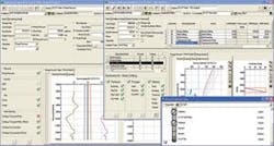
To examine all the alternatives and converge on this optimal well design, it is vital that all engineering analysis functions be fully integrated within the same application as the well-planning functions and reference a common drilling database (Fig. 2). The Paradigm Sysdrill application provides such a unified drilling engineering solution. Use of a common data model ensures that any changes to the well path and well path-related data, such as the pressure profile, are immediately available to all engineering analyses, removing the need for data exchange or replication.
Direct extraction of 3D volume data along a well path allows the pore and fracture gradient profiles specific to that wellbore to be used directly for calculating the required casing seats, based on user-specified criteria such as kick and trip margins.
Three examples
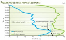
In the first example, the initially proposed sidetrack from the closest offset (B2) well represents the shortest well path to the target. Engineering analysis quickly reveals, however, that it is not feasible to drill because it would require three casing strings within an almost impossibly small mud-weight window (Fig. 3).
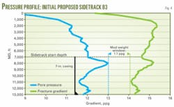
A sidetrack from the bottom of the B3 well provides a better, although longer, option than the original B2 sidetrack. The mud-weight window is extremely tight, however, likely making it difficult and expensive to drill due to the constraints on mud weight.
Fig. 4 shows the pressure profile of the initial proposed sidetrack, B3. It appears from the pressure distribution within the well curtain that a kickoff from higher in the well could potentially avoid the high-pressure area above the B3 target. This indeed turns out to be the case, and doing so significantly widens the mud weight window.
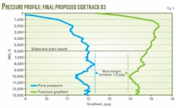
Fig. 5 shows the pressure profile of the final proposed sidetrack, B3. In this case, the longer sidetrack proves to be the easier to engineer and probably the most economical to drill of the options reviewed.
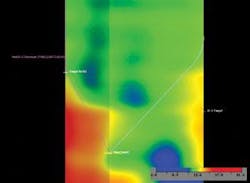
This image from the 3D volume shows pressure profiles along the initially proposed sidetrack B2 on the left and final selected sidetrack B3 on the right (Fig. 6).
Fig. 6 shows pressure profiles along initially proposed sidetrack B2 on the left and final selected sidetrack B3 on the right. In a few steps, we have evaluated options that range from nondrillable to challenging, through to a relatively straightforward sidetrack plan, just on the basis of spatial variations in 3D pressure data.
Design efficiency
Further engineering analysis would determine the actual drilling and casing programs required to drill this well in accordance with the geological constraints and company engineering design policies. This analysis, in some cases, might identify further issues or constraints that necessitate additional changes to the planned trajectory.
It is therefore essential that the well-planning and engineering functions are delivered as a unified solution, tightly integrated with a 3D visualization application, so that the workflow can be quickly rerun as required to optimize the well design. Integrating multi-disciplinary applications is the key to well-design efficiency.
Acknowledgment
We thank John Turvill for his contribution to the article, originally published in a Paradigm newsletter.
The authors
Robert Innes ([email protected]) is director for well planning and drilling at Paradigm, Aberdeen. He has also served as Paradigm’s business development manager for drilling and Middle East operations manager in the UAE and sales and marketing manager for Sysdrill. He holds a higher diploma in computing science from The Robert Gordon Institute of Technology. He is a member of Society of Petroleum Engineers.
Doug Gilmour ([email protected]) is drilling applications specialist at Paradigm, Houston. He has also served as technical author at Sysdrill. He holds a BSc in geology from the University of Edinburgh and an MA in geographical information systems from the University of Leeds. He is a member of SPE.
