New developments in fiber optics benefit offshore surveillance
The digitization of the oil and gas industry continues to gain momentum, transforming how reservoirs are monitored for both energy production and carbon storage. Machine learning, automation, and emerging sensor technologies have become as indispensable as drilling rigs, risers, and pipe wrenches in today’s offshore field. Perhaps the greatest example of the ongoing transformation is the proliferation of fiber optics for downhole distributed acoustic sensing (DAS) and distributed temperature sensing (DTS). Within a few years, fiber optic sensing has enabled new insights into fluid movement across the reservoir and into the well and provides assurance that wells are performing correctly and safely. Fibers are now used in diverse applications such as:
- Static bottom-hole pressure surveys
- Through-tubing leak location
- Injection profiling with liquid and gas flow allocation
- Cement-cure evaluation
- Vertical seismic profiling (VSP)
- Well-fracture stimulation monitoring
Fiber deployment limitations include high equipment costs and installation complexity for permanent installations (especially offshore), and long-distance signal strength attenuation. Several new approaches, however, decrease the cost of fiber surveys and extend the deployed range of fibers in subsea installations. This article describes examples of recent critical fiber-survey developments.
Injection monitoring
Tight carbonate reservoirs require extended-reach horizontal laterals up to 20,000 ft for economic development. Maximum production is limited in tight reservoirs by drilling fluid invasion damage and low permeability, requiring effective acid stimulation to achieve low-skin completions. Uniform stimulation across the entire lateral, however, is difficult due to differences in permeability, formation damage, and rock-property variation.
Acid stimulation with coiled tubing (CT) is an inefficient method of affecting proper acid diversion in long-reach wells. Conventional CT can be length limited by lock-up, and heavy-weight coil can be weight limited for transport from boat to deck.
To address these concerns, ExxonMobil Corp. and Abu Dhabi National Oil Co. (ADNOC) implemented a limited-entry liner (LEL) design for bullhead acid stimulation.1 The liner contains a small number of perforations separated by swell packers to act as a diversion device for the acid. During bullhead injection, high pressure-drop across the jets ensures that a single area does not take excessive fluid (thief zone), maintaining injection uniformity across the lateral. The perforations produce high-velocity acid jets (100–200 ft/sec) to remove damage and stimulate the formation. The liner can be tuned by changing perforation size and density to better match reservoir characteristics and to remove heel-bias stimulation.
Real-time fiber optic surveillance monitored stimulation effectiveness with DTS-DAS (though results from the DAS survey were not reported). The fiber monitored 0.5-m intervals along the lateral with 1-2 sec (1-0.5 hz) pulse repetition frequency. Thermal and acoustic profiles provided qualitative and quantitative diversion measurements of the LEL.
During injection, temperatures change along the lateral. Cooler areas are where fluid has entered the formation, and areas at or close to reservoir temperature have not received much stimulation. After shut-in, recovery rates back to reservoir temperature infer location and volume of stimulation fluid entering the formation.
A 12,000-ft horizontal water-injector well was completed in a tight reservoir offshore Abu Dhabi with an LEL. The reservoir was multi-layered limestone about 120 ft thick with variable amounts of dolomite in the lower portion. Permeability thickness is variable along the lateral with porosities ranging from 22% to 19%. Reservoir pressure is mostly uniform along the lateral.
The lateral section was divided into 18 compartments separated by swell packers and blank pipe sections. The number of LEL holes ranged from 4 to 20 for each of the compartments. A total of 166 4-mm holes were distributed non-uniformly across the lateral.
The objectives of the installation were to improve well injectivity by removing post-drilling formation damage through high-rate bullhead stimulation, qualitatively evaluate effectiveness of LEL lower completions in providing uniform mechanical diversion of stimulation fluids using DTS-DAS, and quantify stimulation fluid allocation using DTS-DAS data.
Bullhead injection was around 15-20 bbl/min with 15% HCl, equivalent to about 40 gal/ft across the entire lateral. The fiber optic line was run on CT in a single run. With the well shut in, CT was run in-hole, reaching lock up at 13,680 ft MD, and pulled by hydraulic tractor to 21,000 ft TD. With CT at target depth and the well shut in, a first DTS baseline profile was acquired, followed by the acid job.
Stimulation was through the CT-injection tubing annulus. A pre-flush was pumped at 19 bbl/min with 500 bbl of friction-reduced water, followed by the main acid treatment at 19-23 bbl/min with 10,000 bbl of 15% HCl, followed by the post flush at 23 bbl/min with 2,100 bbl of friction-reduced water. The first DTS cool-down profile was acquired over the course of the entire stimulation job. Once the acid stimulation injection was stopped, a DTS warm-back profile was acquired showing thermal recovery of the well. The well remained shut in until a second DTS baseline profile was acquired. The well was put back into injection, pumping 3,000 bbl of injection water at 10.4 bbl/min through the production line.
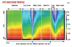
Fig. 1 shows a heat map of temperature changes along the lateral from DTS measurements during the stimulation job. Temperatures ranged from 80° F. to 150° F. The plot shows baseline before pumping, main acid treatment, shutdown and warm-back second baseline, post-stimulation water injection, and post-water injection warm-back.
The initial baseline shows static lateral temperatures ranging from about 115° F. (green) to 140° F. (red) from heel to toe, respectively. During stimulation injection, blue areas of cool fluid appeared on the map. The dark blue portion of the map of acid injection shows that acid effectively reached the toe of the well. Once the well was shut in, temperatures increased as the reservoir returned to its natural geothermal state. The second baseline did not warm back to the same level as the initial baseline at the heel, indicating that sufficient fluid was pumped into the formation to cool it even through the warm-back cycle. Data show that the subsequent injection of water reached the toe, again indicating that effective stimulation occurred across the lateral. The fiber optic system was instrumental in revealing the detailed injection profile, which could not be achieved with conventional discrete pressure or temperature gauges alone.
Seismic survey
Multi-well 3D DAS VSP has become a viable alternative to ocean-bottom node (OBN) seismic imaging due to lower total cost of ownership and opportunity for more frequent 4D DAS imaging over the life of the asset. A subsea deepwater reservoir monitoring DAS installation was investigated by bp PLC and Lytt Ltd. for Atlantis Phase 3 field extension in the Gulf of Mexico to determine if the system could reduce VSP acquisition costs.2
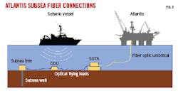
Subsea wells’ fiber optic installations must operate over several km of subsea cabling and through a critical chain of wet connects on the subsea tree (which provide optical continuity from one fiber to the next in installations that cannot be completed with a single continuous fiber), including several high-loss connections on the sea floor. The DAS interrogator is topside, in the semisubmersible platform production quarters (PQ), and connects to the subsea well through a fiber optic umbilical, a series of subsea umbilical termination assemblies (SUTA), and an optical distribution unit (ODU) (Fig. 2).
Installing the DAS interrogator on the PQ rather than adjacent to the subsea tree reduces cost, simplifies data transfer, allows system upgrades, improves reliability, and reduces power and communication interface requirements within the subsea production system. The resultant wet connects and junctions, however, attenuate DAS pulse and backscattered light and significantly reduce light intensity over a single-fiber installation. Up to an order magnitude signal loss (-10 db) is not uncommon in one direction compared with an equivalent single-fiber installation. Combined with the return light path, optical signal can drop 100-fold (-20 db).
At Atlantis, these losses were mitigated by using an engineered fiber with a hundred times more reflectivity than conventional fiber. Tests showed that a system with standard single-mode fiber in a 15-km downhole cable yielded almost no DAS backscatter signal after high losses induced by the optical feed-through system (OFS) containing wet connects. The engineered single-mode fiber with high backscatter yielded a signal equal or superior to the fiber signal upstream of the OFS.
Qualifying tests of the DAS system began with an offshore survey on the PQ, measuring loss and performance of the existing Atlantis umbilical and remotely operated vehicle (ROV) wet connects. An umbilical emulator replicated these optical parameters and was connected to the interrogator through a performance test rig built in accordance with SEAFOM test standards. Optical tests and optimizations carried out over 6 months, ranged from best, expected, and worst-case losses for the optical path.
The interrogator measured light intensity using multiple fiber gauge-lengths and confirmed that the signal properly scaled with chosen gauge-length. The engineered fiber underwent accelerated lifetime testing in a high-temperature, hydrogen-rich environment to demonstrate long-term survivability.
In addition to cost benefits, DAS is advantageous over conventional seismic surveys in that it is permanently deployed, providing VSP surveys whenever convenient, without needing to align seismic vessel timing with intervention work. This results in more frequent 3D imaging yielding increased 4D granularity over the life of the field.
Disposable-fiber leak detection
More than 30% of all active wells exhibit sustained annulus pressure which rebuilds after bleed-off, indicating persistent communication with the reservoir. Other common integrity issues include barrier or valve malfunction or corrosion failure of completion strings, conductors, or casing. Integrity surveys are now a high priority for all operators due to high costs of well workovers, production loss, and well integrity.
Downhole real-time surveillance locates fluid movement and identifies where and what type of remediation work will be effective. Cost, time, and risk constraints, however, have prohibited widespread use, and most leaks are still detected from wellhead gauge data or sporadic spectral noise logs (SNL), conveyed either on wireline for real-time data or slickline in memory mode.
Logs are limited by excessive noise from movement of the tool within the wellbore. The SNL tool must be stationary to obtain useable signals from leaks, and the tool must be repositioned frequently, leading to delays and difficulty identifying precise leak locations. On wireline, only a fraction of the acoustic signal can be transmitted via copper wires. In slickline memory mode, leak detection is performed blind, and data is only recovered after the tool is retrieved. Wireline logs typically take 2-3 days to rig up, run, and rig down, with over a week for full interpretation of the data.
Leak detection surveys have been improved using fiber -in-metal tube (FIMT) which encapsulates fibers within a 1/8-in. tube for slickline or CT deployment. The entire wellbore can be logged using both single-mode (SM) and multi-mode (MM) fibers for DTS and DAS simultaneously, while the FIMT remains static in the wellbore. Integrity information is available over all depths and as a function of time to detect leak direction and velocity, and data are collected at surface for immediate analysis while the FIMT is in the well.
Fiber optic leak-detection surveys are completed more quickly than standard SNL, but rig up, rig down, and running time remain the same as conventional logging operations. FIMT does not provide the same acoustic sensitivity as contemporary spectral noise logs and requires capital investment in a specialist cable, so while it has proven effective in many applications, uptake to date has been limited.
These limitations are overcome by deploying a disposable fiberline intervention (FLI) system.3 In this system a bare fiber, without encapsulation, is spooled out in a well from a small, weighted probe. Both are disposable at the end of the survey.
The system consists of a single use fiber deployment probe, pressure-controlled release assembly, hand pump, and fiber optic data-acquisition system. The probe is available in 1.625-, 2.00-, or 2.75-in. OD versions up to 25,000 ft in length. The probes weigh less than 16 lb and measure up to 5 ft (1.5 m) long. Both SM or multimode MM fibers are available for simultaneous DAS and DTS acquisition. A single engineer runs the entire operation. The complete loadout, including pressure control equipment (PCE), can be packed in a half-height 8 ft container.
FLI does not feed cable into the well. Fibers are held at a pre-determined point at the top of the PCE and, as the probe free-falls into the well, bare fiber plays out behind, adhering to the wall of the wellbore for continuous, real-time, depth-specific logging. The probe can also be pumped into the well to access highly deviated and horizontal wellbores.
Deployment is much faster than wireline, usually reaching depth in less than 2 hours. Without metal encapsulation, FLI has superior acoustic and thermal sensitivity compared with conventional protected fiber.
FLI was selected by a leading international operator to investigate sustained annulus pressure in a North Sea offshore well. The well had been in production since 1982 before being released for abandonment in 2019. In preparation for abandonment, a plug was set at around 9,000 ft before cutting tubing above to circulate fluid into the well. Fluid returns could not be established, and a shallow-set plug was deployed. Following pre-abandonment operations, A-annulus pressure increased from 0 psi to 1,070 psi. Upon opening the well, 943 psi of pressure was observed in the tubing, indicating either a shallow leak path or failure of the shallow-set plug.
The objective for FLI was to determine the leak point with real-time DAS and DTS profiles to enable barriers to be reestablished while bleeding down B-annulus pressure. High-frequency sound is attenuated more quickly than low-frequency, and the change in frequency indicates the depth of the leak relative to the fiber sensor. Additional depth identification comes from changes in temperature. A tubing leak, for example, could generate a change in local temperature next to the fiber, but an annulus leak may register on acoustic but not temperature sensing fibers, as there is a physical barrier between the leak and the temperature sensing fiber.
Two disposable distributed-acoustic and temperature-sensing fibers were deployed into the well via a 2 ¾-in. diameter probe to a total depth of 8,850 ft. The probe reached total depth 16 min after launching at surface and the gas-liquid interface was identified at 3,900 ft by a change in the descent velocity of the probe and verified with the acoustic coupling signature. Once ambient acoustics from deployment had diminished, baseline DAS and DTS logs were recorded for reference. The leak was induced by bleeding-off from the B-annulus valve. Leak detection was completed in 25 min, capturing fluid movement from a source at the top of the 7 5/8-in. liner, moving both up the well towards a side pocket mandrel and down to a milled window.
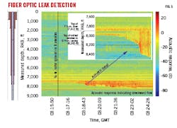
Fig. 3 shows the baseline acoustic log and the effect of opening the B-annulus valve. There is an obvious and almost immediate acoustic event starting at 7,960 ft, with flow progressing downward over time. The inset detail shows a flow front travelling both up and down the completion at a velocity of about 2.2 ft/s. The upward flow rises to the top of the 7 5/8-in. liner at 7,912 ft, while downward flow travels to 8,200 ft which coincides with the top of a milled window in the 9 5/8-in. casing. At this point the flow front accelerated to 20 ft/s with increased acoustic energy, before returning to a flow rate of 2.2 ft/s at 8,360 ft and continuing down the wellbore to a depth of about 8,660 ft.
A temperature gradient obtained by DTS throughout the well showed no obvious thermal responses associated with the pressure bleed-down of the B-annulus, indicating that there was no leak path through the tubing.
After bleeding down the B-annulus, there was no further evidence of flow, and the acoustic response was like the original baseline. This established that once the pressure differential had diminished the leak was no longer present. It also confirmed that the leak was at a single point in the well and that there were no other leak paths present within the wellbore or completion. FLI proved to be a cost-efficient means of detailed logging for leak detection, and survey data allowed the operator to make well-informed and efficient remediation decisions before well abandonment.
Long-range subsea monitoring
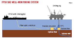
Operators now seek to push DTS-DAS technology into subsea completions with long tiebacks, but optical limitations historically have restricted this application. Initial subsea DAS concepts called for power-intensive interrogator units located adjacent to subsea trees, introducing multiple installation, maintenance, accessibility, and synchronization problems. Topside-deployed DAS systems, such as shown in Fig. 4 with the interrogation unit located on a floating production, storage, and offloading (FPSO) vessel, avoid such problems. The resultant extended fiber length and multiple wet connects, however, introduces signal attenuation, as outlined in the seismic survey application.
Sampling rate (or bandwidth) also suffers in standard subsea DAS installations if sensing a single long fiber. To acquire valid DAS data, only a single laser pulse can traverse the sensing fiber at any given time. If two or more laser pulses traverse the sensing fiber at the same time, their backscattered light interferes with each other, corrupting the data stream. Two-way travel time of light in fiber is about 10 ns/m, requiring a 50 ms delay between pulses for a 5 km fiber installation. This results in a sampling rate of 20 khz, which is formally sufficient for VSP rendering during which marine seismic sources typically operate below 100 Hz.
VSP, however, requires upgoing wavefields to have a high signal-to-noise ratio (SNR) to enable robust 3D and 4D imaging. Also, to obtain DAS data every meter along the wellbore, the DAS interrogator must digitize data at high sampling frequencies. Any signals above the DAS pulse repetition rate are sensed but aliased, meaning that, as the DAS pulse repetition rate is reduced, noise-power spectral density is increased. To obtain maximum SNR, DAS pulse repetition rate must be maximized.
A well with a nominal 5-km downhole fiber, for example, has a 20 khz DAS pulse repetition rate, achieving 10 khz acoustic bandwidth. This is sufficient for both seismic and other reservoir diagnostics such as production profiling, leak detection, and solids production. The extended subsea fiber configuration in Fig. 4, however, will have a pulse repetition rate of 4 khz, assuming a typical subsea layout of 18-km sensing fiber in the tieback and 4.5 km of downhole fiber. This produces a 2 khz bandwidth and SNR is decreased by about 7 db. This is not sufficient for DAS applications such as flow regime discrimination, leak detection, or sand ingress detection.
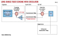
Fig. 5 presents a novel subsea DAS solution deploying a proximal circulator assembly in the topside and a remote circulator assembly in the optical flying lead (OFL) of the subsea tree.4 The dynamic and static umbilicals contain two transmission fibers between the FPSO and tree. The circulators are passive three-port optical devices designed to direct light entering any port to exit the adjacent port. The remote circulator is contained in a nitrogen-purged, one atmosphere cannister along the OFL, terminated at either end with optical wet-mate connectors. The connectors link the subsea tree’s remotely operated vehicle panel and the drill center’s optical distribution unit (ODU).
The topology in Fig. 4 limits the sensing fiber to only that below the remote circulator; the other fibers simply carry the information. Since the upgoing transmission fiber is carrying pure backscattered light, light amplification can be accomplished with an erbium-doped fiber amplifier (EDFA) optimally matched to the dynamic range of the DAS interrogator’s receiver.
Fig. 5 shows the circulator assembly installation with EDFA in the return fiber. A forward-propagating laser pulse entering Port 1 of the remote circulator assembly from one fiber in the tieback (provided by the topside circulator) exits Port 2 and enters the downhole fiber. Only relevant in-well backscattered signal light from the fiber within the wellbore returns along the same wellbore fiber to the circulator at the tree where the in-well signal light is steered to Port 3 of the circulator for its return trip in the second fiber to the FPSO.
Using two fibers for the long tie-back connection and dividing incoming and outgoing light between them effectively eliminates that portion of the optical train from frequency restrictions. In effect, the circulators render the tie-back invisible to signal delay (but not to signal strength decay), and the system has the 20 khz repetition rate of a 5 km dry-tree fiber installation.
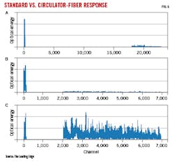
Fig. 6 shows response plots for the standard system with single fiber in the tieback (A) and the circulator system without EDFA (B) and with EDFA (C) in the return fiber. In test (a), a 4-khz signal was sent though the system per standard 25-km tieback and well-fiber system. The gap between the surface circulator (near Channel 0) and first channel response represents the distance between the pulse sent out and the first channel (depth) of interest for downhole data acquisition.
Pulses sent through System B at 12.5 khz resulted in 4-db SNR improvement over the standard system. The gap decreased between the channels at the surface interrogator and the first signal response because the circulator effectively took 18 km of tieback out of the loop, and the residual gap represents only the amount of fiber from the remote circulator to the first depth of interest in the downhole fiber. System C, using EDFA, was like System b in time but improved in signal. EDFA improved signal by 3.0 db which represented 7.0-db improvement over base case.
An onshore field trial using standard and enhanced single-mode fibers was deployed behind casing in a lateral well with a 3.35-km vertical section. Before deployment, the enhanced single-mode fiber was verified to yield 10-db gain in SNR. The subsea DAS system included the interrogator, topside circulator, 12 km of transmission fiber, remote circulator, connectors, and splices simulating distribution through four drill centers. A standard dry tree (or land) DAS system was also included for comparison with the subsea system.
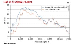
A 45,000-lb vibroseis source swept at 6-96 hz with zero offset and offset locations. The source controller was synchronized to the DAS VSP systems. Fig. 7 shows SNR for dry-tree vs. subsea-tree shot records, obtained by computing signal strength from root-mean-square (RMS) energy in the first break and noise level from the RMS energy of the signal in the first window before the first break. SNR degrades in both cases as a function of depth, primarily because seismic signal strength energy dissipates from spherical spreading and intrinsic earth attenuation.
The subsea system outperforms the dry-tree system with respect to SNR, even including the extra 12 km of umbilical fiber and 6 db of connector insertion loss. The remote circulator assembly obtained shot records at the same 12.5-khz sampling frequency as the dry tree system. Without circulators, a subsea system would be expected to acquire sampling at 5 khz, degrading SNR about 4 db over the circulator system.
References
- Sau, R., Kiyoumi, A., Amin, A., Correia, G, Barghouthi, A., Almheiri, A., Wheatley, E., Ali, Y., Seabrook, B., Angelese, R., and Shuchart, C., “Bullhead Stimulation and First Real-Time Fiber-Optic Surveillance in Extended-Reach Horizontal Laterals to Maximize Reservoir Recovery in a Giant Offshre Carbonate Oil Field Abu Dhabi,” Abu Dhabi International Petroleum Exhibition and Conference, Abu Dhabi, UAE, Nov. 11-14, 2019.
- Naldrett, G., Soulas, S., Gestel, J-P., and Parker, T., “First Subsea DAS Installation for Deep Water Reservoir Monitoring,” European Association of Geoscientists and Engineers, conference proceedings, First EAGE Workshop on Fibre Optic Sensing, Vol. 2020, March 2020, pp.1-5
- Green, A., “New leak detection technology shows promise in a range of applications,” Offshore, Vol. 82, No. 1, January, 2022.
- Ellmauthaler, A., Seabrook, B., Wilson, G., Maida, J., Bush, J., LeBlank, M., Dupress, J., and Uribe, M., “Distributed acoustic sensing of subsea wells,” The Leading Edge, Vol. 39, No. 11, November. 2020, pp. 801-807.
About the Author
Alex Procyk
Upstream Editor
Alex Procyk is Upstream Editor at Oil & Gas Journal. He has also served as a principal technical professional at Halliburton and as a completion engineer at ConocoPhillips. He holds a BS in chemistry (1987) from Kent State University and a PhD in chemistry (1992) from Carnegie Mellon University. He is a member of the Society of Petroleum Engineers (SPE).
