Integrated risk assessment improves Colibasi field drilling performance
Mohamed Halafawi
Laza˘r Avram
Petroleum-Gas University of Ploiesti
Ploiesti, Romania
El Dilbani Ali
Geolog Co.
Bucharest, Romania
Ayham Mahnna
GSP Offshore Co.
Constanta, Romania
Addressing problems encountered in previous offset wells has helped improve drilling of new Colibasi field development wells onshore in southern Romania’s Dambovita county. Drilling data, anti-collision management, hazard identification, and risk assessment were analyzed for each section of the proposed development wells to evaluate pressure profiles, well integrity, and casing stress checks. Required drilling time for new wells was estimated and compared to offset wells. Recommendations were made for better borehole cleaning practices and optimum drilling parameters.
Background
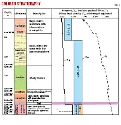
Wells drilled in Colibasi encountered a stratigraphic column with Oligocene epoch deposits belonging to the Paleogene, represented by the Oligocene, and the Neogene, represented by the Helvetian, Meotian, Pontian, Dacian, and Levantin lithofacies (Fig. 1). Meotian and Helvetian facies are stratiform, and Oligocene facies are anticlines. The deposits are heterogeneous siliceous sandstones. Field tectonics are complex with flanks affected by longitudinal and perpendicular cross faults which partition the structure in over 50 hydro-dynamically isolated blocks. Oil accumulations are in the Meotian hanging wall, Helvetian hanging wall, Meotian footwall, Helvetian footwall, and in the Oligocene.
Well 268 Colibasi will be drilled in Block VI, targeting the major productive oil formation in the Oligocene, which produces from several sandstone complexes (Kliwa Superior I, II, III and IV). To determine geological and geophysical conditions for future development wells, data were analyzed from offset wells 260 Colibasi (2008), 259 Colibasi (2012), 259 ST (2018), and 261 Colibasi (2009), drilled in the same block as 268 Colibasi.
Targets for 268 Colibasi are Kliwa Superior II with Kliwa I as secondary objective from the Colibasi central section. The well will be drilled in the same block as 259 Colibasi, 260 Colibasi, and 261 Colibasi. The well will produce oil and associated gas. Expected service life is 24 years.
Hazard identification, risk assessment
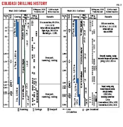
Colibasi offsets 259, 259-ST, 260, and 261 are in the zone targeted by new development wells, and their data were used to fully analyze and evaluate all anticipated drilling conditions. Fig. 2 shows statistics for selected offset wells with respect to well profile, time, wellbore problems, drilling parameters, formation types, corresponding mud types, and operations. From these analyses, pore pressure gradient, fracture pressure gradient, best mud type, and optimized mud weights were determined for the new well.
Anti-collision management
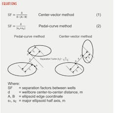
One of the main drilling objectives for new wells is optimizing trajectory and reservoir entry while avoiding collision with existing wells. An anti-collision system was developed based on offset data. Its active management will improve wellbore stability and select best hole-cleaning practices for new wells. A separation factor (SF) is used to delineate safe distance between two wells considering survey error and using ellipses of uncertainty (Equations 1 and 2). A separation factor above 1 indicates that wells will not intercept. Minimum allowed safety factor is SF = 1.5 along the entire length of the reference well.
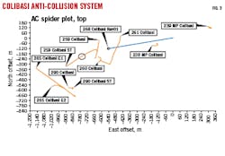
A spider plot constructed based on true vertical depth (TVD) and northeast coordinates determined aberration from the planned wellbore and vicinity with offset wells. Fig. 3 shows the borehole plan view based on anti-collision methods and deviation calculations for 268 Colibasi. Nearest existing wells include:
- 261 Colibasi (abandoned), 52.28-m center-to-center (CTC) spacing, 2.88 SF at 2,085-m MD.
- 238 MP Colibasi (on artificial lift), 37.86-m CTC spacing, 3.32 SF at 1,089-m MD.
- 259 Colibasi (on artificial lift), 101.14-m CTC spacing, 6.78 SF at 2,371-m MD.
- 260 Colibasi (on artificial lift), 151.77-m CTC spacing, 8.55 SF at 2,259-m MD.
Both CTC and SF were calculated from the nearest offset well with an SF < 10.
Wellbore integrity, risk analysis
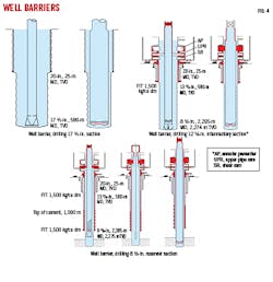
Drilling plans for 268 Colibasi include selected well barriers to maintain hole integrity (Fig. 4). A risk assessment (RA) and mitigation matrix was created based on lessons learned from all offsets. Detailed plans per hole section are discussed below.
For drilling the 17 ½-in. section, mud specific gravity (SG) based on expected pore pressure is the primary barrier. Casing will be 13 3/8-in., and the section will initially use 1.15 SG equivalent mud weight (EMW) based on offset well pore pressure data. A casing float valve is the secondary barrier.
RA identified potential hazards for the hole section which includes lost time from flow lines clogged with surface hydrating clays and BHA bit balling. Mitigation of risk includes flow line access widows for cleaning, pretreating mud with surfactant and KCL to avoid balling, and using flow rates and mud rheology based on offset data for good cuttings evacuation.
Shock absorbers and controlled drilling parameters will mitigate bit bouncing. Mud degradation can be minimized with mud treatments to assure decreased Ca and increased pH, with circulation as necessary to maintain mud properties.
Tight spots while running casing, resulting in induced losses from surge pressures or failure to reach bottom, can be controlled by avoiding threshold ledges in the well trajectory, reaming ledge intervals if recorded, circulating for hole cleaning, and pumping and displacing hi-vis pills before pulling out of hole (POOH ) before running casing. Additionally, tight spots can be minimized by controlling running speed, running surge simulations before the casing job, using reamer shoes and casing running tools, and washing or reaming down.
For drilling the 12 ¼-in. intermediary section, mud is the primary barrier. Several secondary barriers, however, will be used: a stab-in safety valve pressure-tested up to 350 bar, drill string proper makeup with visual observation, drilling blow out preventer (BOP) pressure-tested to 170 bar every 14 days, spool wellhead pressure-tested at 150 bar, surface casing pressure-tested to 170 bar, and surface-casing cement formation integrity test (FIT) for a 1.50 SG EMW formation.
RA for this section identified excessive reaming and circulation non-productive time as the primary risk resulting from poor initial hole cleaning due to the S-shape trajectory. Hole instability is also a concern. Mitigation strategies include using planned flow rates, ECD management, and best hole cleaning practices. Mud treatment with bridging materials will assure 8-9 viscosity readings at 6 rpm. The stand will be reamed before connection. High rpm (>120) and maximum flow rates will be used during circulation, and mud will circulate through shakers as necessary to clean criteria before POOH.
Mud contamination from gypsum, anhydrate, and salt is also a concern. These affect mud rheology and will be addressed with mud treatments to decrease Ca and increase pH, with circulation as necessary. Tight spots while running casing are also identified risks, and mitigation strategies are the same as in the 17 ½-in. section.
Casing for the intermediate section will be 9 5/8-in. and, as above, the primary barrier is mud with a specific gravity based on expected pore pressure. Multiple secondary barriers include reverified BOP and spool wellhead pressure tests, visual inspection of casing float valve, properly mounted casing running assembly, surface casing pressure-tested to 62 bar, and FIT for surface-casing cement for a 1.50 SG EMW formation.
For drilling the 8 ½-in. reservoir section, an additional primary barrier to mud weight is drill-in open hole fluid weight with specific gravity based on expected pore pressure. Secondary barriers differ from the previous section as drilling pay is more complicated. These barriers include stab-in safety valve pressure-tested to 350 bar, proper make-up of drill collar with visual observation, non-return valve, drilling BOP, spool Wellhead A with access valve and casing hanger (all three pressure-tested to 250 bar), and FIT for intermediate-casing cement for a 1.50 SG EMW formation.
Wireline must be performed before casing the 8 ½-in. section, and primary barriers are the same as drilling the section. Secondary barriers include wireline stuffing box, drilling BOP, spool Wellhead A with access valve, casing hanger, wireline lubricator, landing string (all pressure tested to 255 bar), and FIT for intermediate-casing cement and 1.50 SG EMW formation test. Casing will be 7-in. with primary barriers the same as wireline primary barriers. In terms of secondary barriers there is a slight difference, a stab-in safety valve and casing float valve will be installed and pressure-tested to 255 bar instead of the wireline stuffing box and wireline lubricator.
RA of this section identified mud losses in the depleted Kilwa IV formation as the primary concern. Mitigation strategies are to pump LCM pills, reduce flow rate, monitor hole cleaning, perform intermediate circulations during wiper trips, and run liner to shear fluid.
Stuck pipe and gas influx are additional concerns, with risk of NPT due to reaming and overpull, or losing BHA in hole with subsequent fishing operations. Risk minimization includes reaming every stand prior to connection, using higher flow rates for hole cleaning, pumping high viscosity pill if required, monitoring hook-load before and after connection, and minimizing connection time. Additionally, problems can be avoided by using a light BHA, keeping mud weight within planned parameters, treating mud with lubricants, and minimizing sliding.
Gas influx is controlled through increasing mud weight, using bridging material in the drilling fluid, and using gas migration control additives in the cement slurry.
Casing stress check
Casing stress checks enable quick, systematic, and accurate evaluation of casing wear limits, design safety factors, minimum-cost design solutions, and comprehensive triaxial design with burst, collapse, and axial loadings at installation and throughout service life. They are also used for assessing loads, stress, and buckling solutions for vertical and directional wells. Colibasi 260 casing sections were analyzed for design limits, multiple load pressure, and axial and tri-axial safety factors. Safest zones, loads, and safety factors which will maintain 268 Colibasi integrity were identified and included in the drilling program.
Drilling performance
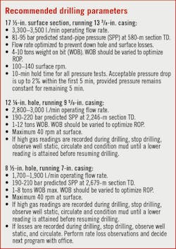
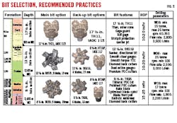
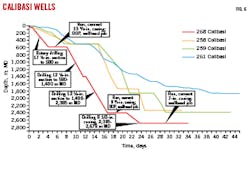
Based on the above considerations, Box 1 and Fig. 5 list recommended drilling parameters for each casing section. Fig. 6 shows expected drilling time for 268 Colibasi compared to historical offset well times using these recommended practices incorporating hazard identification, RA, drilling parameters optimization, wellbore integrity, directional survey, and anti-collision management. Casing sections are separated out in the analysis, and wellhead job refers to any job that does not include drilling, cementing, or casing. Typical examples are installing the BOP, IT maintenance, cutting excess of the last casing joint, welding casing head, and installing filling tools. Optimum anticipated time to 2,679-m MD will be 34 days compared with an average of 50 days for offset wells.
Bibliography
Adams, N.J., “Drilling Engineering: A Complete Well Planning Approach,” PennWell Publishing Co., Tulsa, Okla.,1985.
Azar, J.J. and Samuel, G.R., “Drilling Engineering,” PennWell Corp., Tulsa, Okla., 2007.
Bourgoyn, A.T., Millheim, K.K., Chenevert, M.E., and Young F.S., “Applied Drilling Engineering,” Society of Petroleum Engineers, Richardson, Tex., SPE Textbook Series, Vol. 2, 1991.
Algburi, H., Halafawi, M., and Avram, L., “Offset-well data improve Zubair wellbore stability”, Oil & Gas Journal, Vol. 118, No. 1, Jan. 6, 2020, p. 38.
Halafawi, M., Ra˘da˘cina˘, D., and Avram, L., “Casing Wear Prediction in Horizontal Wells,” Petroleum and Coal Journal, Vol. 62, No. 2, 2020, pp. 395-405.
Halafawi, M., Tahair, M., Wiercigroch, M., and Avram, L., “Optimum Well Trajectory Design Based on Numerical Optimization Method PSO Algorithm and Wellbore Stability,’’ Petroleum and Coal Journal, Vol. 62, No. 1, 2020, pp. 114-128.
Hossain, M.E. and Al-Majed, A.A., “Fundamentals of Sustainable Drilling Engineering,” Scrivener Publishing LLC, Wiley, Canada, 2015.Mitchell, B.J., “Advanced Oil Well Drilling Engineering Handbook and Computer Programs,” Mitchell Engineering, Lakewood, Colo., 10th ed., Rev. 1, 1995.
Mitchell, R.F. and Miska, S.Z., “Fundamentals of Drilling Engineering,” Society of Petroleum Engineers, Richardson, Tex., SPE Textbook Series, No. 12, 2011.
Mohiuddin, M.A., Khan, K., Abdulraheem, A., Al-Majed, A., and Awal, M.R., “Analysis of wellbore instability in vertical, directional, and horizontal wells using field data,” Journal of Petroleum Science and Engineering, Vol. 55, No. 1-2, January 2007, pp. 83-92.
Rabia, H., “Well Engineering and Constructions,” Entrac Petroleum Ltd. Consulting & Training, London, 2001.
The authors
Mohamed Halafawi ([email protected]) is a Ph.D student in the department of drilling, extraction, and transportation of hydrocarbons, Petroleum-Gas University of Ploiesti (UPG). He has a BSc (2011) and MSc (2014) in petroleum engineering from Cairo University and is a member of SPE and the General Association of Engineers in Romania (AGIR).
Lazar Avram ([email protected]) is professor and the head of the department of drilling, extraction and transportation of hydrocarbons at UPG. He is also a visiting professor at universities in France, Greece, Lebanon, Morocco, and Tunis. He holds BSc and MSc degrees from UPG and a Ph.D from IFP School, France.
El Dilbani Ali ([email protected]) is a field engineer at GEOLOG International. He holds a BSc (2017) in petroleum and gas engineering at UPG and a MSc (2019) in petroleum engineering at the University of Salford, Manchester, UK.
Ayham Mhanna ([email protected]) is a drilling engineer working with GSP Offshore which operates in the Black sea. Mhanna has a BSc (2017) and two MSc degrees (2019) in oil and gas from UPG and is currently a Ph.D student at the university.
