Low-cost modifications boost capacity, crude processing flexibility
James W. Jones
Turner, Mason & Co.
Dallas
Frank Simmons
Delek Refining Inc.
Tyler, Tex.
Tony D. Freeman
KP Engineering LP
Tyler, Tex.
A project design that maximizes use of existing equipment in expanding a refinery's crude oil processing capacity, and limits equipment additions to only those necessary, improves timelines and yields while reducing costs.
Delek Refining Inc., a subsidiary of Delek US Holdings Inc., Brentwood, Tenn., with the assistance of Turner, Mason & Co. (TM&C) and KP Engineering LP (KPE), recently completed a project to expand crude oil processing capacity by 20% at its refinery in Tyler, Tex. (OGJ Online, Mar. 26, 2015).
Leading up to and throughout its February-March 2015 refinery turnaround (T/A), Delek made major modifications to several process units at the refinery to increase capacity to 75,000 b/d from 60,000 b/d.
The Tyler refinery, which processes primarily low-sulfur Permian basin crude oil, now can run an additional 12,000-14,000 b/d of crude,with two-thirds of the incremental production volume ultralow-sulfur diesel (ULSD).
In addition to correcting other bottlenecks and deficiencies throughout the plant, the extra volumes of light tight Permian basin oil processed have increased the American Petroleum Institute (API) gravity of feedstock historically handled at the site.
This article, the second of two, elaborates on the specific modifications made to simultaneously increase the refinery's overall capacity by 20%, improve recovery of distillate products, and enable processing of lighter crude.
The first article (OGJ, Sept. 7, 2015, p. 104) discussed how a decision by Delek's management to embrace a nontraditional approach to project development and execution that involved collaboration with its refining consultant, TM&C, and a preselected engineering, procurement, and construction (EPC) contractor, KPE, ensured the refinery revamp's success.
Project description
The Tyler expansion project, which included major modifications to the refinery's crude distillation and distillate hydrotreating (DHT) units, also involved modifications to the vacuum unit tower, naphtha hydrotreating unit, and saturate gas plant, as well as installation of additional cooling for the delayed coking unit's fractionator.
Infrastructure additions were minor and consisted of the following:
• A dozen interconnecting pipes.
• A DHT feed booster pump in the tank farm.
• Associated electrical modifications.
• Two new truck lanes for diesel loading at the refinery's product terminal.
Crude unit
The crude unit received a new preflash tower and its associated overhead system, increasing throughput to 75,000 b/d.
Fig. 1 shows modifications made to the crude unit as part of the revamp.
The capacity expansion further required a series of modifications to the existing crude oil preheat train and the addition of several new heat exchangers.
Preheat train modifications improved overall heat recovery and addressed the hydraulic issues associated with increased capacity, and also corrected several existing product cooling issues within the unit.
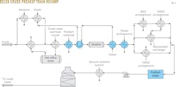
Fig. 2 shows the Tyler refinery's preexpansion preheat train configuration.
Installation of new preflash tower overhead crude exchangers and a new diesel-crude exchanger occurred downstream of the existing crude tower overhead-crude exchangers and upstream of the desalter. The existing kerosine-crude and diesel-crude exchangers were moved from downstream of the desalter (the "hot train") to upstream of the existing crude tower overhead exchangers (the "cold train"). The existing diesel pumparound (P/A) exchanger was placed in gas oil service, with new diesel P/A exchangers and another diesel product exchanger added to the hot train.
Fig. 3 shows the new preheat train configuration following the expansion project.
While the preheat train revisions moved this unit from below-average to above-average heat recovery, the existing equipment and piping layout heavily influenced the new configuration and generally excluded a best-in-class design. But large improvements in hydraulic capacity and heat recovery were still achieved for a reasonable cost, consistent with TM&C's design philosophy for the project.
The new preflash tower was installed downstream of the heavy vacuum gas oil (HVGO) P/A exchangers. Modifying the crude flow to these exchangers from two-pass to three-pass allowed crude oil vaporization and minimized the resulting increase in pressure drop, removing the need to modify the existing crude oil charge pumps.
The existing flash drum, which formerly received oil directly from the desalter, became the preflash tower-bottoms surge drum. As a result, no modifications were needed to the high-pressure desalted crude charge pumps, which continue to feed the furnace from this drum.
Several crude unit product pumps received new impellers and, in a few cases, larger motors; however, only one new pump was added. The new preflash overhead reflux-product pump that was required commonly is spared by the existing spare crude tower overhead product pump. TM&C's design plan for the unit revamp, which focused on limiting additional new motors, allowed Delek to avoid expensive modifications to the unit's electrical substation.
Vacuum unit
Modifications to the refinery's vacuum unit were limited to the upper section of the tower.
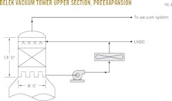
Fig. 4 shows the vacuum unit tower top before the revamp project.
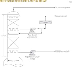
The existing 8-ft diameter top was replaced with a new 10-ft diameter section that measures about 25 ft high so that a diesel fractionation section could be incorporated in the new tower. This allowed the top product to become heavy diesel instead of LVGO. Although the modification required new upper P/A pumps, the existing upper P/A cooling system remains unchanged.
Adding an LVGO draw at the bottom of the new upper section minimized light gas oil falling down the tower, which might have led to unwanted cooling of the HVGO section. Provisions were made, however, to recycle this stream back to the HVGO P/A return line for periods when it is more economic to fully maximize distillate recovery.
Repurposing the existing unit's upper-P/A pumps allowed LVGO to be sent from this new draw to the FCC.
Fig. 5 shows the Tyler refinery's newly reconfigured vacuum unit tower top.
As a result of the revamp, atmospheric gas oil (AGO) from the crude unit now runs to the HVGO P/A return, along with any recycled LVGO, to introduce this diesel-rich stream into the vacuum tower for additional distillate recovery.
Alongside reducing additional duty for the vacuum unit furnace, this approach prevents extra vapor traffic in the flash zone. The result is a high degree of diesel recovery from the AGO and LVGO streams previously sent directly to the FCC.
Separate from the modifications described above, Delek elected to make other changes to the vacuum unit that also became part of the overall scope of work. While unrelated to the expansion effort, these changes resulted in pump, heat exchange, and tower modifications that were included in the overall project cost.
Diesel hydrotreater
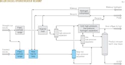
The largest changes made to the refinery as part of the project occurred at the DHT, which before the revamp, was a single-train unit (Fig. 6). These modifications represent more than half of the project's process unit, or inside battery limits (ISBL), costs.
The project called for modifications that would create a hybrid dual-train unit with a capacity of 36,000 b/d.
While Delek had previously charged as much as 25,000 b/d to its single-train DHT to make ULSD, this practice came at a steep price. The existing reactors were originally sized to produce 14,000 b/d of low-sulfur diesel. Operating at higher charge rates to produce ULSD sharply reduced catalyst life. This was partly due to considerably higher hydraulic rates, which both lowered liquid hourly space velocity (LHSV) and created a large pressure drop across the reactor. This pressure drop, in turn, lowered reactor-outlet partial pressure below levels that encourage the degree of aromatic saturation necessary for desulfurizing tough-to-reach sulfur molecules.
Modifications made to the unit as part of the revamp improved its performance by:
• Doubling catalyst volume to improve LHSV.
• Restoring the ability of the preexisting reaction train (Train 1) to operate at a reasonable pressure.
• Creating a second reaction train (Train 2) more suited to desulfurizing cracked feedstock.
Fig. 7 shows the Tyler refinery's new hybrid dual-train DHT.
Given some flexibility by Delek in how Train 2 could be configured, TM&C designed the new train with a somewhat higher pressure and larger reactors so that as much as 100% of cracked distillate feed could be directed to it.
The design approach led to large improvements in Train 1's ability to desulfurize by removing most of the tough sulfur in its new feed.
Since Delek previously installed refurbished hydrogen compressors that were oversized for DHT service, the revamp did not require costly upgrades to the hydrogen compression section. The higher-pressure (and higher-purity) makeup hydrogen stream, however, ran to Train 2 to enable a higher hydrogen partial pressure and system operating pressure in the train receiving most of the cracked feed.
Lower-pressure recycle hydrogen supplements Train 2's treat-gas needs by entering the system downstream of the furnace and as quench hydrogen. All remaining recycle hydrogen serves as treat gas for Train 1.
Excess hydrogen leaves Train 2 via the back-pressure controller on the new hot separator and joins the Train 1 hydrogen stream from its hot separator.
At this point, the hydrogen circuit becomes a common system using the existing DHT's heat exchange, cooling, and amine treating equipment, but with one important exception. The revamp project included the addition of a new common air cooler for the effluent hydrogen stream from both hot separators.
Along with providing the additional effluent hydrogen cooling necessary to improve the performance of the refinery's preexisting exchangers and trim coolers, this new air cooler replaced a preexisting air cooler that, before the revamp, had an insufficient maximum operating pressure and limited both the maximum recycle compressor suction pressure and the maximum operating pressure of Train 1. Replacement of the air cooler fully restored Train 1's maximum operating pressure and desulfurizing capability. The preexisting air cooler was repurposed providing additional Train 1 ULSD-product cooling.
Hot separator liquid from Train 2 now travels directly to the existing product stripper. Retraying the tower's lower section accommodated the large increase in liquid load. The tower's upper section and overhead system remained unchanged.
A parallel stripper-bottoms line with a new product-Train 2 feed exchanger and product air cooler accommodated 50% of the total 36,000-b/d ULSD product flow. This stream rejoins the existing stripper-bottoms stream entering the existing trim coolers. A new ULSD product filter and coalescer replaced undersized preexisting equipment, which was reused to condition incoming cracked-distillate feed. Before the expansion project, Delek already had replaced a small salt dryer with a much larger vessel that has ample ability to handle the increased ULSD production.
Dismantling an idle light-naphtha isomerization (isom) unit immediately adjacent to the DHT created the plot space for the new reaction train.
The new Train 2 reaction system includes a third charge pump, commonly spared by the preexisting Train 1 spare charge pump; a feed drum (previously the isom product stripper); a new three-shell feed-effluent exchanger; and a new furnace, in addition to the previously mentioned new reactors and hot separator.
Project scope included converting the isom separator into a cracked-distillate surge drum, with two new cracked-distillate booster pumps also added to inject this feedstock into the new Train 2 feed-ULSD product exchanger, where it is preheated with a portion of the straight-run distillate from the existing feed system. This combined stream enters the Train 2 feed drum.
While feeding the cracked-distillate stream exclusively to Train 2 helps maximize overall catalyst life, the new configuration also allows for a portion of the stream to go to Train 1 when necessary. Should Train 2 be down while Train 1 operates, all cracked distillate can go to Train 1 via the new cracked-feed system, or the two cracked steams can be blended, as before, with the straight-run distillate feed in the tank farm.
NHT, saturate gas plant
The naphtha hydrotreater (NHT) and saturate gas units required only minor modifications to accommodate increased naphtha production from the higher crude runs.
The NHT, which was previously modified to its hybrid dual-train configuration to increase capacity to 22,000 b/d from 14,000 b/d, was modified further to 28,000 b/d. A third charge pump and another NHT-feed debutanizer-bottoms exchanger also were added (Fig. 8).
Converting the NHT's furnace from single-pass to two-pass created a truly dual-train unit up to the hot separator.
The purge-hydrogen stream from the DHT was routed to the NHT to increase the available makeup-hydrogen volume.
Before the revamp several bottlenecks limited the Tyler refinery's NHT, while the saturate gas stripper, at its prior charge rate, operated flooded.The addition of a new, parallel stripper (albeit not operated identically) as part of the project accommodated the higher charge rate as well as unloading the preeexisting stripper.
Unlike the preexisting stripper, which received only cool feed, the new stripper primarily feeds hot separator liquid along with a small volume of cool feed for top reflux.A new steam reboiler accompanies the new stripper, but both strippers share the preexisting overhead system, which became possible once the preexisting stripper stopped operating in a flooded state.
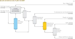
The saturate gas unit, which is integrated with the NHT, required other modifications to handle the increased volume of desulfurized full-range naphtha.
The lower section of the debutanizer was retrayed with high-capacity trays.
Fig. 9 shows the Tyler refinery's modified saturate gas unit.
The refinery's original naphtha splitter, which was idled when Delek installed its more sophisticated Mobil Source Air Toxics (MSAT) splitter to keep benzene precursors out of the reformer feed, was returned to service. This tower operates as a depentanizer to maintain the MSAT splitter charge rate below its maximum capacity. Using this configuration Delek also increased gasoline-blending flexibility during the summer when producing low-RVP finished gasoline.
The pentane-rich stream from the old splitter now goes to the current light-naphtha pressurized storage system, while the much lower RVP-MSAT splitter overhead stream can be blended easily into low-RVP summer gasoline. This production path reduces the volume of light naphtha Delek needs to sell or store during the volatile organic compound (VOC) control period. It may also help eliminate potential octane giveaway associated with producing regular gasoline for 10%-ethanol addition, since the new MSAT overhead stream represents a low vapor pressure-low octane blend stock ideal for subgrade blending.
Coker
While TM&C typically tries to avoid expensive modifications to delayed coking units, increasing the distillate recovery from the heavy-coker gas oil stream at the Tyler refiner was a priority. The modification, however, was easily accomplished by adding an air cooler to the distillate P/A circuit.
A new, low-cost air cooler replaced an idled, preexisting gas oil air cooler in the coking unit. Because the preexisting air cooler was much larger than the refinery's required distillate P/A exchanger duty, the project team chose to split the new tube bundle to also add air cooling to the fractionator overhead condensing system. This modification increased overall coker capacity since the total cooling available at the fractionator was the primary unit bottleneck. Delek completed this modification during an earlier coker outage and verified its new ability to fully recover coker distillate.
The additional overhead cooling also reduced the heat load on the unit's cooling tower, lowering summer-cooling water supply temperatures by 10° F. and greatly reducing water-side fouling on the preexisting fractionator overhead condenser.
Delek's Tyler crude unit is now processing 75,000 b/d of 42-43° API gravity crude oil, with the NHT and DHT able to operate at their new respective charge rates.
The refinery also improved its recovery of distillates, as evidenced by the near absence (<5%) of distillate (e.g., material lighter than 650° F.) remaining in the FCC feed compared with 25-30% when the expansion project was proposed.
The project benefited from the using existing equipment throughout the Tyler plant that was either oversized for its service or underused due to bottlenecks in other parts of the refinery. The project team's approach of maximizing the use of existing installations and keeping new additions limited to reasonable investments was an important factor in developing the project
