Moving caustic injection point improves crude unit operations
Saudi Aramco was experiencing serious fouling and corrosion in the second preheat train in the crude unit in its Yanbu refinery. The problems were due to underdeposit, inorganic deposit, and high-temperature sulfide corrosion, which led to pressure buildup and tube leaks in the crude unit.
Relocating the caustic injection point to upstream of the crude heater allowed the refiner to overcome heat exchanger fouling and solve maintenance problems.
On average, this project is saving $80,000/year in maintenance costs. The cost avoidance of dumping diesel to fuel oil is about $1.5 million/year.
This article discusses the problems faced after the relocating project and lessons learned.
Background
Saudi Aramco’s Yanbu refinery is a hydroskimming refinery with a capacity of 235,000 b/d. Crude passes through three preheat stages (series of heat exchangers) before entering the crude heaters. After the first preheat stage, water is added to the preheated crude before it enters the desalters.
A 3°Baume (Be) caustic solution is injected upstream of the desalters to neutralize acids formed. Also, a 3°Be caustic is injected downstream of the desalters for corrosion control.
Since Yanbu started up in 1983, the second preheat stage exchangers had a history of active corrosion and fouling problems. Aramco’s Consultant Services Department (CSD) strongly recommended implementing a best practice, which was to relocate the downstream caustic injection to upstream of the crude heaters from downstream of the desalters to eliminate corrosion and fouling in the second preheat exchangers.
Process overview
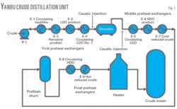
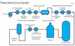
The crude distillation process (Unit V04) involves the crude charge flowing through preheating, desalting, charge heating, crude column distillation, and naphtha fractionation. The crude unit consists of two identical preheat trains (A and B).
Fig. 1 shows a flow diagram of the Yanbu refinery crude distillation unit.
Crude charge passes through the first-stage preheat train, which is a series of four heat exchangers:
- E-1. Crude-circulating naphtha exchanger.
- E-2. Crude-kerosine product exchanger.
- E-3. Crude-light diesel oil (LDO) product exchanger.
- E-4. Crude-circulating LDO No. 1 exchanger.
After the first preheat train, crude flows to the desalters at about 120-125° C. and is mixed with wash water before entering the desalters. From the desalters, crude passes through the second-stage preheat train that heats the crude to its flash temperature in a series of three heat exchangers:
- E-5. Desalted crude-circulating LDO No. 2 exchanger.
- E-6. Desalted crude-heavy diesel oil (HDO) product exchanger.
- E-7. Desalted crude-cold reduced crude exchanger.
Liquid from the flash drum, V2, is pumped in the flash drum bottoms pump, P2, to the final preheat section:
- E-8. Desalted crude-circulating HDO exchanger.
- E-9. Desalted crude-hot reduced crude exchanger.
Preheated crude finally enters crude charge heaters, H-1A and B, where it is heated to crude column flash-zone requirements. The heater outlet temperature is controlled at 375° C.
Caustic injection
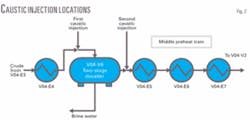
After the first preheat section, water is added to and thoroughly mixed with the preheated crude using a preset mixing valve before it enters the first-stage desalter, V6A. Crude leaves the desalter and is further mixed with fresh water before entering the second-stage desalter, V6B.
The 3°Be caustic is injected upstream of the desalters to neutralize acids formed during the hydrolysis of salt. Caustic injection is controlled to maintain a pH value of 6-7 in the brine water effluent. The 3°Be caustic is also injected downstream of the desalters for corrosion control and to control the chloride content in the crude distillation tower overhead.
Fig. 2 shows the caustic injection locations.
Fouling, corrosion problems
Aramco had observed, since the refinery started up in 1983, that the middle preheat exchangers V04-E5, E6, and E7 had active corrosion and fouling problems, caused by underdeposit, inorganic deposits, and high-temperature sulfide corrosion, which lead to pressure buildup and tube leaks.
Underdeposit corrosion products are activated mainly by elevated temperatures on the inlet shell-sides of the exchangers, which lead to underdeposit corrosion due to partial vaporization of the water and light ends in the crude. The high temperature of the crude passing through the second preheat train is another factor that can accelerate such fouling.
Because Arabian Light crude has a high sulfur content of 1.5-2.0%, and due to high operating temperatures, the environment is ideal for high-temperature sulfur corrosion.
The research and development department’s analysis of inorganic deposits inside the tubes of V04-E7 showed that about 88 wt % of the plugging material was the iron sulfide corrosion products pyrite and pyrrhotite, 9 wt % was water soluble salts halite-NaCl, and 3 wt % was calcium carbonate. These inorganic deposit materials are the major contributors of fouling inside the tube, which led to a pressure buildup.
The high temperature of crude passing through the second preheat train is another factor that accelerates fouling. A two-stage desalter after the first preheat train was designed to minimize salt in the feed. The outlet design for salt is less than 1 lb/1,000 bbl. This target was not attainable due to low desalter efficiency, caused by an inadequate water wash rate and a low desalter residence time.
The water wash injection, according to industrial best practices, should be 3-5 vol % to assure that the required salts are dissolved compared with the existing injection rate, which is around 2.9 vol %. A correct desalter residence time is also important in ensuring that no water carryover occurs. The calculated residence time of the Aramco desalter was 11.5 min at 235,000 b/d, which is less than the design rate of 15 min at 170,000 b/d.
We concluded that downstream caustic injection acts as a catalyst for fouling and underdeposit corrosion, which increases the pressure drop and leakage in the middle preheat exchangers.
Middle preheat exchangers
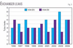
We found that most of the tube leaks were in the top portion of the bundle, especially for V04-E5 and V04-E6. This is due to the high heat flux at that location.
Fig. 3 shows the number of tube leaks for V04-E5 and V04-E6.
For V04-E7, most of the problems associated with these exchangers were uniform thinning, localized attack, and erosion corrosion, according to Aramco’s CSD.
The inspection records showed that the V04-E5 and V04-E6 tube bundle metallurgy was upgraded for both trains to 12% Cr steel from carbon steel and 5 Cr-1/2 Mo due to the high frequency of tube failures. Only three exchangers for V04-E7 were upgraded to 5 Cr-1/2 Mo while the others are carbon steel.
CSD confirmed that the original carbon provided a satisfactory service life of about 20 years and upgrading the subject tube bundles to 5 Cr-1/2 Mo would not fully eliminate the erosion-corrosion problems.
Caustic injection relocation
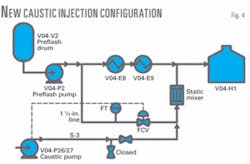
CSD recommended relocating the downstream caustic injection to 66 m upstream of the V04H1A/B heater from its previous location downstream of the desalters. This would enhance overhead corrosion control of chlorides and would eliminate the corrosion and fouling problem in the second preheat exchangers.
The design included adding a crude slipstream to the caustic stream before it is injected in the 14-in. heater charge line to eliminate water vaporization and caustic deposition. In addition, an interlock system would trip the caustic pumps if the crude slipstream flow is low.
The premixed caustic injection point is 66 m upstream of the crude charge heater passes. This is to allow the premixed caustic to mix well with the bulk crude.
In addition, Monel 400 was used to construct the piping downstream of the crude slipstream-caustic mixing point. The quill and the static mixer were also constructed of Monel 400. The new caustic injection point was started up on May 2006.
Fig. 4 shows the new caustic injection configuration.
Post relocation project
Aramco observed that frequent fouling of the second preheat exchangers was eliminated. Testing and inspection of eight desalted crude heat exchangers V04-E5 and E6 were completed on July 2007. An initial visual inspection revealed that all components were in good condition without any significant mechanical damage.
A 100% magnetic particle inspection, conducted on the internal weld seems of the shells, channel box, and covers, did not reveal any defects. All exchangers passed initial and final hydrostatic tests.
Aramco experienced major savings due to this project. Before, on average, 10 exchangers/year were fouled and leaked. Mechanical cleaning, hydrotesting, and maintenance labor cost $8,000/exchanger. On average, this project saves $80,000/year in maintenance costs.
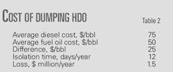
Furthermore, this project prevented the frequent isolation of V04-E6 A/B. The isolation of this exchanger resulted in the dumping of HDO product to the fuel oil stream, reducing the production of diesel (Table 1).
On average, the V04-E6 isolation occurred 10 times annually, with an average of 3 days of maintenance work. The cost of dumping HDO to fuel oil is $1.5 million/year (Table 2).
On average, this relocation project is saving $1.8 million/year.
Corrosion
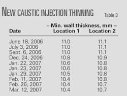
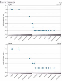
After relocating the caustic injection on May 2006, inspection data at the new caustic injection locations revealed unacceptable corrosion rates in the 14-in. crude lines upstream of the heaters for Trains A and B.
Table 3 and Fig. 5 show that the estimated localized corrosion rates were 0.6 mm/5 months for Train A (at the bottom) and 0.4 mm/5 months for Train B (at the top).
CSD, P&CSD, and Yanbu plant personnel conducted a root-cause analysis to focus on potential causes and actions necessary to minimize corrosion. This included examining the detailed inspection data (ultrasonic testing, radiographs, scans, and infrared), as well as design, fabrication, and operational parameters.
The parties concluded that the damage mechanisms for each train were different and most likely scenario for the attack was:
- Metal losses in the 14-in. crude lines were due to general corrosion attack from the caustic, which attacked the pipe wall before it was diluted with crude. This would explain the highly localized corrosion seen immediately downstream of the injection point in the 6 o’clock position for Train A and in the 12 o’clock position for Train B.
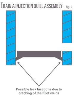
- For Train A, the parties suspected that there are leaks of partially undiluted caustic on the 14-in. carbon steel line from the root of fillet welds of the quill end plate that is causing corrosion (Fig. 6). Infrared surveys showed localized areas of much lower temperatures.
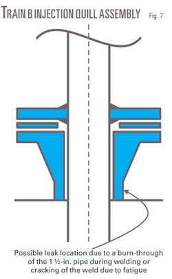
- For Train B, the parties suspected that improper mixing was allowing some of the caustic to drift upwards to the crude piping, leading to localized attack. The end plate weld in this case appeared to be solid and intact. Also, we cannot be certain if there could be a small leak in the flange weld that could allow top of the line corrosion (Fig. 7).
null
null
Further work
The investigation team believes that the leak on the quill plugged itself. In the meantime, Aramco is conducting biweekly ultrasonic testing scanning on the new injection points to ensure integrity of the crude line. Furthermore, Aramco will take the first coming shutdown opportunity to visually inspect the injection quill for replacement or upgrade.
The author
Mohammed Eid ([email protected]) is a process engineer in the operation engineering unit in Saudi Aramco’s Yanbu refinery. He has 5 years’ experience in refining processes. Currently, Eid works in the refinery’s crude distillation unit. He holds a BS in chemical engineering from Arizona State University and an MBA from Regis University, Denver.
