Shot-coke mitigation study improves revenues for Chinese refinery
Chaolin Liang
Guandong University of Petrochemical Technology
Maoming, China
Keng H. Chung
North Huajin Chemical Industries Group Corp.
Panjin, China
A comprehensive study of operating conditions at commercial cokers of a China Petroleum & Chemical Corp. (Sinopec) subsidiary and a pilot-scale delayed coker yielded recommendations for new operational parameters that the refinery has implemented to help mitigate shot-coke formation and, as a result, sharply boost profitability of its coking business.
Chinese refineries primarily have used delayed cokers to produce metallurgical coke for steel manufacturing. As crude oil feedstock becomes heavier and higher in contaminants such as sulfur, nitrogen, and metals, refiners increasingly are using delayed cokers to convert petroleum residue into light fractions and remove most contaminants as byproduct coke.
Refineries, however, are facing the growing challenge of spherical shot coke forming in delayed coking units. Typically 2-10 mm in diameter but in some cases as large as a basketball, shot-coke formations in a delayed coker cause blockage of the unit's feed system and transfer lines, resulting in unstable process operation and a shortening of run cycles.
With the market price of shot coke much lower than that of typical petroleum coke, Sinopec subsidiary Sinopec Maoming Petrochemical Co. Ltd.'s 470,000-b/d refinery in China's Guangdong province participated in a study designed to examine new approaches to mitigating shot-coke formation as a way to improve both stability and economics of its delayed coking processes.
Background
There have been previous attempts to understand shot-coke formation.1-5 High-quality coker feeds with less contaminants and low Conradson carbon residue (CCR) do not form shot coke regardless of unit operating conditions, while lower-quality coker feeds have been found to form shot coke under certain operational circumstances. Due to the highly turbulent and erratic flow regime inside a coke drum, however, there is no analytical model which accurately predicts the likelihood of its formation.
Located on China's southern coast, Sinopec Maoming's refinery includes two 20,000-b/d delayed cokers. As one of the country's most modern and complex refineries, Maoming also is one of the only equipped to effectively process a heavy crude slate, most of which it imports from the Persian Gulf and South America.
Coker feeds
The coker feed at Maoming refinery is a blend of various refinery bottoms streams that consist of solvent deasphalting-derived (SDA) pitch as well as atmospheric and vacuum residue (VR) Depending on crude shipment schedules and inventory levels at the refinery's tank farm, Maoming's typical coker feed consists of four main types:
• Feed A is a blend of Saudi heavy oil, Napolitano crude VR, and SDA pitch.
• Feed B is a blend of Soroosh crude VR and Iranian crude VR.
• Feed C is a blend of Saudi heavy oil and Iranian crude VR.
• Feed D is a blend of Saudi heavy oil and Saudi crude VR.
Distinctly different from Feeds C and D, Feeds A and B are inferior feedstock. The viscosities of Feeds A and B are an order of magnitude higher than those of Feeds C and D. Feeds C and D have lower CCR, asphaltenes, and metals contents but higher hydrogen-to-carbon (H/C) ratios.
Table 1 shows the properties of the four types of coker feeds at Maoming refinery.
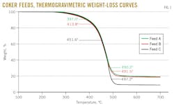
To determine thermal reactivities of Feeds A, B, and C, the study used the STA 449 F3 Jupiter thermogravimetric analyzer (TGA) by Netzsch-Gerätebau GmbH, Selb, Germany.
Fig. 1 shows the TGA weight-loss curves of Feeds A, B, and C as a function of temperature. The initial inflection-point temperature shows the devolatilization propensity of each feed sample.
TGA analyses show initial inflection-point temperatures of Feeds A and B (397.0° C. and 413.8° C., respectively) much lower than Feed C's (451.6° C.), indicating that Feeds A and B are more volatile than Feed C. Terminal inflection-point temperatures of the three coker feeds are all within a range of 490-497° C. The asymptotic weights (fixed carbon) above 500° C. of Feeds A and B are similar but higher than that of Feed C.
High amounts of fixed carbon in Feeds A and B result from their high-CCR and asphaltene content.
Maoming's performance
To establish a basis of comparison for commercial and pilot unit data, the study first measured process performance of various coker feeds under similar severe delayed-coking process conditions at the Maoming refinery.
To ensure optimal production yields for sampling purposes, severe reaction conditions implemented at the cokers included high temperature, low pressure, and a low bottoms-oil recycle ratio.
Table 2 (Columns I-IV) compares the process performance of various coker feeds at the refinery.
Yields of coker products from Feeds A and B are similar to each other but different from those of Feeds C and D, with coke yields of Feeds A and B higher than those of Feeds C and D due to their high-CCR and asphaltenes content.
As operational data from the Maoming refinery indicate, Feeds C and D yield sponge cokes, regardless of coker operating conditions, in accord with previous findings.4 5 But feeds A and B form shot coke under severe reaction conditions. By reducing reaction severity slightly, however, Feeds A and B form sponge cokes (Table 2, Col. V-VI).
The yields of coker products of Feeds A and B varied only slightly, regardless of shot or sponge-coke formation, showing the type of coke formed from Feeds A and B (inferior feedstock) as dependent on coker operating conditions.
Coke properties
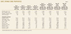
Using samples obtained from commercial coking runs at the Maoming refinery, the study next examined properties of shot and sponge cokes derived from Feeds A, B, C, and D (Table 3).
Analyses of coke samples showed that the properties of coke derived from Feeds C and D are different from those of Feeds A and B. Feeds C and D sponge cokes have higher H/C ratio and Hardgrove Grindability Index (HGI) hardness but lower density and ash, sulfur, and metals contents than coke derived from Feeds A and B.
The low-ash, sulfur, and metals contents of coke derived from Feeds C and D are likely due to lower contaminant content in the feeds.
HGI hardness and H/C ratio of sponge coke derived from Feeds A and B are between those of shot coke derived from Feeds A and B and sponge coke derived from Feed C and D.
Coke morphology
Shot and sponge coke derived from Feeds A, B, C, and D under various commercial coker operating conditions at Maoming refinery next underwent scanning electron microscopy (SEM) analysis using a JSM-6510-LV scanning electron microscope by JEOL Ltd., Tokyo.
The average size of shot coke in commercial coker operations depends on coke-drum vapor velocity. Because average sizes of shot coke in a single coke drum tend to be similar, if large shot-coke particles are formed, all of the shot coke in the drum should be large, and vice versa.
Small shot-coke particles are more spherical. As the size of shot coke increases, the shot-coke particles elongate and become elliptical. Sponge coke typically consists of irregular chunky blocks with tiny holes on the surface due to the release of hydrocarbon gas from the coke's interior.
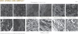
Fig. 2 shows the photographs and SEM micrographs of shot and sponge-coke samples collected from coking operations at the Maoming refinery.
Shot-coke particles derived from Feeds A and B are spherical and 1-8 mm in diameter, with the majority of particles 4-6 mm in diameter. Compared with sponge-coke particles derived from Feeds C and D, sponge coke derived from Feeds A and B has a patchy, dark mosaic appearance.
Microscopic textures of shot coke derived from Feeds A and B are coarse, irregular, three-dimensional lattices,6-8 while microscopic textures of sponge coke derived from Feeds C and D are relatively flat, uniform, and two-dimensional.
While the microscopic texture of sponge coke derived from Feed A resembles that derived from Feeds C and D, Feed A sponge coke also has irregular lattices.
The microscopic texture of sponge coke derived from Feed B closely resembles shot coke derived from Feeds A and B.
A comparison of photographs and SEM micrographs shows that while sponge coke derived from Feeds A and B resembles that derived from Feeds C and D on a macro level, their microscopic texture reveals sponge coke derived from Feeds A and B as intrinsically shot coke (Fig. 2).
Pilot unit
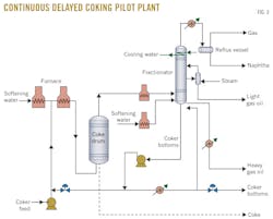
In an attempt to better understand the effects of coker operating conditions on shot-coke formation, the study commissioned construction of a 4.5 kg/hr continuous delayed coking pilot plant to simulate operations of a 150-tonne/hr commercial coker (Fig. 3).
Electrically heated and thermally insulated, the pilot delayed coker consisted of a feed system, an electric feed furnace, an electric steam-generation system, a coke drum, a fractionator, and a coker gas-and-liquid products recovery system.
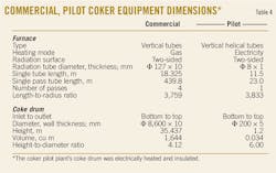
Although the pilot-scale coking unit was orders of magnitude smaller than the commercial coker, the length-to-radius ratios of furnace tubes and height-to-diameter ratios of coke drums were similar.
Table 4 shows a comparison of dimensions for key equipment of the commercial and pilot-scale delayed cokers.
The pilot coker also maintained a similar operating procedure to that of its commercial counterpart at Maoming, with its design calling for up to 12 hr of continuous operation before half of its coke drum would be filled with delayed coke.
The study employed the same Feeds A and B used in testing at the Maoming refinery.
To simulate shot-coke formation in commercial operations, runs at the pilot-scale unit took place under severe reaction conditions.
Pilot experiment
After preheating the pilot-scale coking unit, technicians metered softening water through an electric furnace to generate steam which circulated throughout the pilot unit.
Once the unit reached its targeted operating temperature, warm coker feed travelled through the feed furnace to the coke drum.
Product vapor from the top section of the coke drum next fed into the unit's fractionator for separation into both gas products (dry gas and liquefied gas) and liquid products (naphtha, light gas oil, heavy gas oil, and coker bottoms). Coker bottoms, or unconverted resid, were recycled to the coker feed system.
Similar to a commercial coker, the pilot-scale coker achieved full-resid conversion during continuous process operation, reaching steady state after 1 hr.
Sampling of coker gas and liquid products occurred at 2-hr intervals, and after 11-hr continuous operation, coker feed was discontinued. After cooling the pilot unit down to room temperature, the coke drum was purged with nitrogen gas for 5 min. The top and bottom sections of the coke drum were then disassembled and product coke removed from the drum.
Pilot results
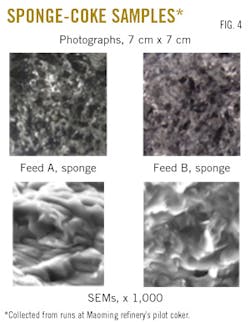
Fig. 4 shows photographs and SEM micrographs of sponge coke samples derived from Feeds A and B during pilot-scale coker runs.
In contrast to coke yields derived from runs of Feeds A and B at the Maoming refinery's coking operations, runs of Feeds A and B at the pilot-scale coker yielded only sponge coke (Table 2, Col. VII-VIII) with the microtexture of shot coke (Fig. 2).
While the use of a pilot-scale coker can be helpful in simulating commercial coking operations for coker product- yield prediction, the study determined it is inadequate for coke's macro-morphological study. Even though various dimensional ratios of the pilot coker were similar to those of its commercial counterpart, the pilot unit's coke-drum vapor velocity was limited to 0.0125 m/sec, an order of magnitude lower than that of commercial coking operations.
Because coke-drum vapor velocity is a critical factor affecting the macro morphology of coke,9-13 shot coke can only be produced with inferior feedstock in commercial coker units. The study nevertheless shows that a pilot-scale coker can be crucial in determining optimal product yields of various coker feeds.
Mitigating formation
After a thorough review of extensive commercial coker process performance data, the study concluded that formation of shot coke with inferior feedstock in commercial coker processes occurs when coke-drum vapor velocity is greater than 0.120 m/sec.
The following guidelines, therefore, can be used to reduce coke-drum vapor velocity:
• Reducing reaction severity (decreasing reaction temperature or increasing pressure) results in fewer vapor coker products, reducing coke-drum vapor velocity.
• Reducing the coker feed rate results in fewer vapor coker products, reducing coke-drum vapor velocity.
• Reducing the amount of water used during online lancing in furnace-tube cleaning reduces flashing of injected water and leads to a concurrent decrease in coke-drum vapor velocity.
Increasing the bottoms-oil recycle ratio can also mitigate shot-coke formation. Since bottoms oil has low-CCR and asphaltenes contents, blending fresh coker feed with a high amount of recycled bottoms oil improves the quality of reacting oil. An increased bottoms-oil recycle ratio, however, reduces the coker's fresh-feed rate, leading to increased coke-drum vapor velocity.
Economic benefit
Shot coke is typically used as a fuel for power generation. Due to its inferior combustion characteristics, however, shot coke is sold at a $60/tonne discount to sponge coke.
Following this study, the Maoming refinery switched 30% of its coker feed to Feeds A and B, which has led to an additional 100,000 tonnes/year of sponge-coke yield, generating additional revenue of $6 million/year.
Acknowledgments
The authors thank China Natural Science Foundation (Grant #21176050) and Sinopec Maoming's refinery for their assistance in this work.
References
1. Siskin, M., Kelemen, S.R., Eppig, C.P., Brown, L.D., and Afeworki, M., "Asphaltene Molecular Structure and Chemical Influences on the Morphology of Coke Produced in Delayed Coking," Energy & Fuels, Vol. 20, No. 3, March 2006, pp. 1227-1234.
2. Siskin, M., Kelemen, S.R., Gorbaty, M.L., Ferrughelli, D.T., Brown, L.D., Eppig, C.P., and Kennedy, R.J., "Chemical Approach to Control Morphology of Coke Produced in Delayed Coking," Energy & Fuels, Vol. 20, No. 3, March 2006, pp. 2117-2124.
3. Kelemen, S.R., Siskin, M., Gorbaty, M.L., Ferrughelli, D.T., Kwiatek, P.J., Brown, L.D., Eppig, C.P., and Kennedy, R.J., "Delayed Coker Coke Morphology Fundamentals: Mechanistic Implications Based on XPS Analysis of the Composition of Vanadium- and Nickel-Containing Additives during Coke Formation," Energy & Fuels, Vol. 21, No. 2, March 2007, pp. 927-940.
4. Douglas, L.D. and Siskin, M., "Molecular Assemblies in Asphaltenes and Their High-Temperature Coke Products Part 1: Initial Molecular Organization," Energy & Fuels, Vol. 22, No. 4, July 2008, pp. 2512-2517.
5. Meng, Z.H., Wang, X.L., and Xiao, J.Z., "The performance prediction of coking by coking feedstock," Shandong Institute of Petroleum Refining Committee, Proceedings of 2009 Technology Exchange Meeting, pp. 27-35.
6. Shui, H.F., Zhao, W.J., and Shan, C.J., "Caking and coking properties of the thermal dissolution soluble fraction of a fat coal," Fuel Processing Technology, Vol. 118, February 2014, pp. 64-68.
7. Chen, K., Liu, H., Xue, Z.X., Li, H.Y., Guo, A.J., and Wang, Z.X., "Co-carbonization of petroleum residue asphaltenes with maltene fractions: Influnce on the structure and reactivity of resultant cokes," Journal of Analytical and Applied Pyrolysis, Vol. 102, July 2013, pp. 131-136.
8. Guo, A.J., Lin, X.Q., Liu, D., Zhang, X.J., and Wang, Z.X., "Investigation on shot-coke formation propensity and controlling of coke morphology during heavy oil coking," Fuel Processing Technology, Vol. 104, December 2012, pp. 332-342.
9. Ellis, P. J. and Paul, C.A., "Tutorial: delayed coking fundamentals," 2000 AIChE Spring National Meeting, Atlanta, Mar. 5-9, 2000.
10. Zh, F., Chen, C.M., Yu, C.X., Wu, L., and Ye, M., "Avoiding Shot Coke in Extra-Heavy Crude Delayed Coking Unit," Petroleum Refining Engineering, Vol. 36, No. 12, December 2006, pp. 11-13.
11. Yang, C.W., "Study on Operation Conditions for Producing No Shot Coke in Extra-Viscous Crude Oil Delayed Coking Unit," Petroleum Refining Engineering, Vol. 39, No. 3, March 2009, pp. 28-31.
12. Wang, A.H. and Huang, A.M., "Measures Taken by Yangzi Petrochemical to Prevent Shot Coke Formation in Delayed Coking Unit," Sino-Global Energy, Vol. 14, No. 10, October 2009, pp. 71-73.
13. Jiang, W. and Zheng, Z.X., "Causes of Shot Coke Formation and Countermeasures," Petroleum Refining Engineering, Vol. 38, No. 1, January 2008, pp. 16-18.
The authors
Chaolin Liang ([email protected]) is a professor of chemical engineering and technology at Guangdong University of Petrochemical Technology, Maoming, China. With more than 30 years of refining experience, he also serves as senior advisor for Sinopec Technical and Management Committee. Liang holds a PhD in chemical technology from East China University of Science and Technology.
Keng H. Chung ([email protected]) serves as refinery advisor for North Huajin Chemical Industries Group Corp. He also acts as a process troubleshooting expert for petroleum operations and actively is involved in developing sustainable heavy oil technologies. Chung holds a BS and MS in chemical engineering from Queen's University, Kingston, Ont., and a PhD in chemical and petroleum engineering from the University of Calgary. He is a registered professional engineer in Alberta, Canada.
