New FCC process minimize gasoline olefin, increases propylene
An FCC process called flexible dual-riser fluid catalytic cracking (FDFCC) can minimize gasoline olefins and increase propylene significantly.
Using available FCC catalysts, the FDFCC unit produces a gasoline with 10-35 vol % olefins, while increasing propylene yield by about 6 wt % points vs. conventional FCC units.
These conclusions are based on demonstration trial runs of a 120,000- tonne/year (tpy) FDFCC unit, which was revamped from an existing residue fluid catalytic cracking unit (RFCCU).
The FDFCC process, developed by Luoyang Petrochemical Engineering Corp. (LPEC), an affiliate of China Petroleum & Chemical Corp. (Sinopec), is designed to minimize olefins in catalytically cracked gasoline, a dominant component of China's gasoline pool.
The process was also designed to maximize propylene production in LPG when necessary.
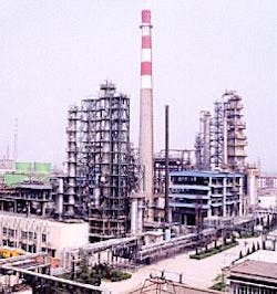
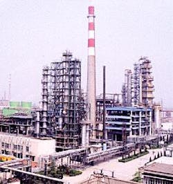
After conducting bench-scale research and pilot plant tests for the FDFCC process in LPEC's laboratory, Sinopec revamped its smallest RFCCU in Qingjiang refinery, Jiangsu, China, into a FDFCC demonstration unit (Fig. 1).
Results reported here are from demonstration trial runs in March and April 2002.
Dual riser-reactor configuration
Because heavy oil cracking and naphtha upgrading optimally occur with different operating conditions, adding a riser reactor to upgrade naphtha in an FCCU is a logical decision.
LPEC, realizing that an added riser could supply an independent reaction area with optimal operating conditions, designed the FDFCC process with two riser reactors.
This process minimizes gasoline olefins, increases gasoline octane, and has the added benefit of a significant increase in propylene yield that compensates for the loss in gasoline yield.
Process description
The FDFCC process has two riser reactors that share a single regenerator. Both reactors naturally share the same catalyst.
Like a conventional FCC riser reactor, the main (cracking) riser reactor cracks atmospheric residue and heavier feeds, whereas the auxiliary (upgrading) riser is designed to upgrade naphthas.
The catalytic cracking reaction is a complicated parallel-series reaction; gasoline, one of the middle products, tends to generate secondary reactions.
Gasoline derived from feed cracking consists mainly of paraffins, olefins, naphthenes, and aromatics (PONA) with the number of carbon atoms varying from 5-10.
The FDFCC upgrading reactor has optimized conditions for the gasoline secondary reaction. The reactor promotes the desired secondary reactions and inhibits the undesired secondary reactions that worsen product distribution.
The desired secondary reactions in the upgrading riser include (using C5-C7 molecules as examples):
Class 1: Hydrogen transfer and isomeration reactions:
4 C6H12 .. 3 C6H14 + C6H6
C6H12 + 3 i-C5H10 .. 3 C5H12 + C6H6
n-C5H10 .. CH3-C4H7
Class 2: Aromatization, alkylation, and condensation reactions:
C7H14 (olefin) .. C7H14 (naphthene) .. C7H8 + 3 H2
2 n-C5H10 .. n-C10H20
C6H6 + C3H6 .. C3H7-C6H5
Class 3: Cracking reactions:
C7H14 .. C4H8 + C3H6
C6H14 .. C3H6 + C3H8
Laboratory research results showed that Class 1 reactions dominate when the temperature is less than 450° C., Class 2 reactions dominate around 500° C., and Class 3 reactions dominate at greater than 550° C.
For maximum gasoline and light cycle oil (LCO) yield, the upgrading reactor should operate with a mild reaction temperature. On the other hand, a high reaction temperature results in more propylene in the cracked gas.
The secondary reactions always occur with sulfur-removal reactions that convert some sulfur compounds in the gasoline fraction into H2S and coke, which lowers the gasoline sulfur.
Additionally, there are no interactions between heavy oil cracking and gasoline upgrading in FDFCC units, which ensures an ideal product distribution for the whole unit.
In an FDFCC unit, extra heat from burning the coke generated from residue cracking is used to upgrade the gasoline, which allows a smaller catalyst cooler. Altering the operating parameters of the upgrading reactor allows adjustment of the product slate.
Typical design patterns
We used several FDFCC unit configurations for different cases. We will describe two typical models that represent extreme examples.
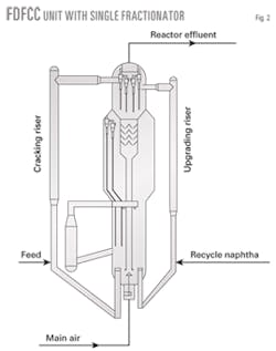
Fig. 2 shows the reactor-regenerator system with a single fractionator.
Although part of the upgraded gasoline is recycled in this design, the process is simplified; therefore, the operation is easier and the capital investment lower.
Upgrading the recycle gasoline can be avoided if the gasoline is from a nearby FCCU instead of the unit itself. This configuration is suitable to large refineries that operate two or more FCCUs.
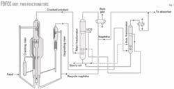
Fig. 3 shows the FDFCC unit with two fractionators. In this model, cracked naphtha from the main fractionator flows to the upgrading reactor.
Upgraded product vapor flows to the auxiliary fractionator where gasoline is separated from the gas product and condensed diesel fraction. Gasoline upgrading efficiency in the two fractionators configuration is higher because no upgraded gasoline returns to the upgrading reactor.
For each configuration, gasoline-upgrading efficiency improves when the unit operates to minimize gasoline olefins. Because olefins concentrate in light cracked naphtha (LCN), it is easier for the upgrading riser to process LCN only rather than full-range naphtha.
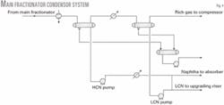
This strategy requires the conversion of the traditional overhead naphtha condenser into a two-stage condenser system (Fig. 4).
Demonstration trial runs
Sinopec converted its smallest RFCCU to an FDFCC unit by setting up a gasoline upgrading reaction system that contains an upgrading riser and catalyst disengager.
Spent catalyst from the upgrading riser enters the regenerator. Vapor effluent from the system flows to the main fractionator after mixing with oil vapor from the main reactor.
We installed a special sample-collecting facility at the gasoline upgrading system effluent; consequently, laboratory analysis can accurately evaluate upgraded gasoline properties and the upgrading reactor yield structure.
Sinopec conducted two trial runs to simulate the typical design configurations. Naphtha was recycled within the unit to achieve the single fractionator configuration (Run 1).
Sinopec could not, however, simulate dual fractionator operations using the revamped unit only—there was no auxiliary fractionator available in the unit. Sinopec fortunately had a 500,000-tonne/year RFCC unit about 200 m from the demonstration unit.
To simulate the two-fractionator FDFCC configuration (Run 2), the upgrading reactor processed naphtha from the RFCC unit. This is equivalent to adding an upgrading reactor in the RFCC unit with an independent auxiliary fractionator.
The refinery keeps a constant single crude supply with no substantial property fluctuations. The FDFCC and RFCC units' feed throughput, catalysts, and operating conditions still had some variations before and during the demonstration runs.
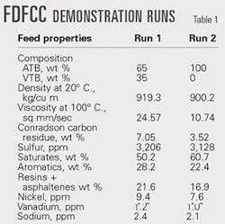
Previous operating data were used as the base case, FDFCC unit data were used for Run 1, and RFCC unit data were used for Run 2. The RFCC unit processes pure atmospheric tower bottoms (ATB) from Subei crude and the FDFCC unit processes a 65-35 wt % mixture of ATB-vacuum tower bottoms (VTB) from the same crude.
Table 1 lists feedstock properties.
Table 2 shows that the equilibrium catalysts used in the demonstration runs are slightly different due to different levels of metal contaminants.
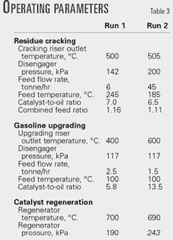
Table 3 shows operating data for the two trial runs. Actual upgrading reactor throughput in Run 2 was 1.5 tonnes/ hr; however, product distributions and properties had to be calculated accordingly.
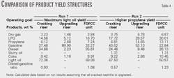
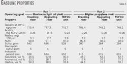
Tables 4 and 5 show trial run data. The data indicate that the process can:
Minimize gasoline olefins. Olefins in the cracked naphtha are 10-35 vol % after the upgrading reaction. The operator can vary the cracked naphtha throughput or operating conditions to adjust gasoline olefins from the FDFCC unit.
Increase propylene significantly. Compared to conventional FCC process, the FDFCC process increases propylene yield more than 6 wt % points when the cracked naphtha is upgraded with severe conditions.
Reduce gasoline sulfur and increase gasoline octane. Sulfur removal varies from 5-25% depending on upgrading conditions. Gasoline octane increased by 0.3 and 2.4 in Runs 1 and 2, respectively.
The condensed diesel has a minimal effect on cracked diesel properties because it accounts for a small fraction of the FDFCC diesel product. We can dismiss its contribution, especially when the diesel will be hydrotreated further downstream.
Minimum naphtha requirement
The FDFCC process produces low-olefin gasoline, but with higher energy consumption and lower light-oil yield. The propylene increase compensates for any lost light-oil production.
A refiner wanting to minimize gasoline olefins should try to lower the amount of cracked naphtha that is upgraded, as long as the product gasoline meets specifications.
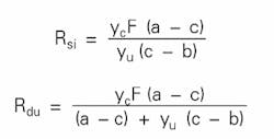
If gasoline olefin is a key control variable, two simplified equations estimate the minimum capacity of the typical FDFCC upgrading reactor:
where:
Rsi = Minimum naphtha recycle rate for a single fractionator, tonne/hr
Rdu = Minimum naphtha recycle rate for a dual fractionators configuration, tonne/hr
a = Olefins in cracked naphtha, vol %
b = Olefins in upgraded naphtha, vol %
c = Required gasoline olefin content, vol %
F = Feed flow rate, tonne/hr
yc = Naphtha yield from the main reactor, wt %
yu = Upgraded naphtha yield from the gasoline reactor, wt %
If the minimum naphtha recycle rate is the primary variable, the dual fractionator configuration is more advantageous because Rdu is less than Rsi with all other variables held constant. Nevertheless, two fractionators constitute a more complex process.
Replacing full-range cracked naphtha with light cracked naphtha can reduce the minimum gasoline reactor throughput.
Longyan Wang is the director of the research institute and a senior engineer at China Petroleum & Chemical Corp.'s (Sinopec's) Luoyang Petrochemical Engineering Corp. (LPEC). He has 17 years' experience in FCC process optimization and additive development. He holds an MS in material chemistry from Lanzhou University, Lanzhou, China. As a part-time graduate, he is studying for a PhD in chenical engineering at Xi'an, China.
Bolun Yang is head of the chemical engineering department and a professor at Xi'an Jiaotong University. His research interests include chemical reactors, separation technologies, and green chemistry. He also served for 5 years as an associate professor at Nagoya University, Japan. Yang holds an MS in chemical engineering and PhD in chemical engineering from Nagoya University, Japan.
Guoliang Wang is vice president and senior engineer at LPEC. He is responsible for the development and application of the FDFCC project. Wang also leads a research and design team that is commercializing a process that produces olefins by heavy oil contact cracking. He holds an MS and PhD in chemistry from the Lanzhou Research Institute of Chemical Physics of the Chinese Science Academy, Lanzhou, China.
Haitao Tang is FDFCC technical manager and a senior researcher at LPEC's refining research institute. His research involves FCC kinetics, catalyst evaluation methods, and refinery sulfur management software. Tang holds a BS in catalysis chemistry from Xiamen (Amoy) University, Xiamen, Fujian, China, and MS in chemical engineering from the University of Petroleum, Shandong, China.
Zhanbao Li is a senior designer at LPEC. He has more than 30 years' experience in engineering and operation of FCC units. He has also served as the technical executive of LPEC's demonstration refinery for more than 15 years. Li holds a BS in chemical engineering from Beijing Institute of Petroleum, Beijing.
Jialu Wei is the chief engineer of Sinopec's Qingjiang refinery. He is responsible for the revamp of the FDFCC demonstration unit. He has more than 20 years' experience in FCCU operations and management. He holds a BS in chemical engineering from the University of Petroleum, Shandong, China.
