Optimizing refrigeration process increases LPGs, reduces costs
Kim Mercier
Juan Ruiz
Encana Corp.
Andrew Lechelt
Bill Chu
Quadra Chemicals Ltd.
Calgary
Using ethylene glycol (EG) for hydrate inhibition in a natural gas refrigeration plant to recover LPGs is common. It's important, however, that the EG regeneration loop be properly designed to accommodate the operating conditions of the refrigeration process. If this is not the case, there may be problems in the process that can affect the plant's performance.
In presenting a case study of one such plant, this article outlines simple changes in an EG regeneration loop that can increase liquid production and decrease operating costs.
Refrigeration involves cooling a gas stream to condense hydrocarbon liquids, and refrigeration plants are common throughout Alberta for NGL recovery. Because of the low temperatures involved, water is also condensed during this process, raising a risk of hydrate formation and freezing.
There are two options to prevent hydrate formation:
1. Dehydrating the inlet gas stream to remove the water before refrigeration; or,
2. Injecting a chemical hydrate inhibitor into the process stream during refrigeration.
The decision between the two options depends on the inlet-gas composition and plant process conditions.
In summer 2013, Encana Corp. completed a study on the refrigeration process at Encana's Corp.'s Clearwater plant in central Alberta. The plant's refrigeration process includes EG injection during refrigeration to prevent hydrates forming.
The study investigated several components of the plant, but the primary changes were made to the EG loop. This article discusses the refrigeration process, the Clearwater study results, the changes implemented at the plant, and the resulting process improvements.
Refrigeration
The purpose of refrigeration at the Clearwater plant is to remove NGL components from the process gas stream. Once gas leaves the inlet separator at the plant, it is introduced to the first part of the refrigeration process: the gas-gas exchanger. This unit cools the inlet gas by cross-exchanging it with cooled gas leaving the refrigeration process en route to sales. Because the gas stream is being cooled, water and NGLs will begin to condense out of the stream.
To prevent water from freezing, EG is sprayed through injection nozzles at the inlet of the gas-gas exchanger tube sheet, contacting the inlet gas stream. The EG is carried through the exchanger with the stream.
In the next component of this process, the chiller further cools the process gas to the required process temperature to allow for the desired hydrocarbon liquids to condense. The chiller is an exchanger involving a propane cooling loop. The process gas enters the tube side, and propane is on the shell side. Additional EG injection occurs in the chiller as well.
From here, the process gas, NGLs, and EG-water mixture enter two two-phase low-temperature separators (LTSs) or a single three-phase LTS, which splits the gas, NGL, and glycol-water. The gas stream leaves through the top of the LTS and flows to sales, NGLs leave the LTS and move for additional processing (as required) to fractionation, and the EG-water mixture (rich EG) leaves the LTS and flows to the glycol regeneration loop.
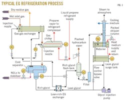
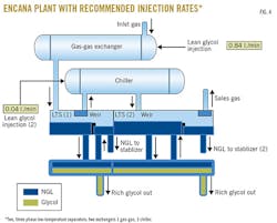
The effectiveness of the refrigeration process depends strongly on the set points and conditions of the EG loop, including EG injection, retention time, and regeneration. Fig. 1 shows a typical refrigeration loop.
Once the rich EG mixture leaves the LTS, it enters the reflux coil in the still column (tube side) for pre-heating. From there the stream flows to the flash tank where the pressure is dropped to about 10% of the process pressure. This allows for degassing of the entrained hydrocarbons from the stream.
The rich EG stream then enters a series of filters (particulate followed by carbon) to remove any contaminants. From there the stream enters the tube side of a lean-rich exchanger (located in the bottom of the EG accumulator) before entering the still column, which distributes it evenly over the packing. As the water is liberated from the stream, the newly lean EG enters the reboiler where it eventually cascades over the weir, flowing into the accumulator.
At this point, the optimal EG-to-water weight ratio is 80:20 (for optimal fluid physical properties). The EG is then pumped back into the process where it is distributed in both the gas-gas exchanger and the chiller, and the glycol loop starts from the beginning again. Before entering the process, the heated, lean glycol goes through an exchanger in the bottom of the glycol surge tank and an exchanger in the bottom of the LTS. The additional heat added to the process aids separation.
Clearwater plant
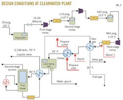
Fig. 2 shows the design conditions at the Clearwater plant. The refrigeration process there occurs after three stages of compression and is followed by a de-ethanizer. NGLs are stored in pressurized bullets and carried by trucks from site, and the gas enters a sales line.
In June 2013, the time of this study, the Clearwater gas plant had a throughput of about 7.5 MMscfd (much less than design capacity), and the gas was compressed to 798 psi before entering the LTS. The NGL production averaged 143 b/d.
(EDITOR'S NOTE: Encana completed the sale of the Clearwater plant to Ember Resources Inc. earlier this year. OGJ Online, Feb. 25, 2015.)
One of the biggest problems at the plant at the time was the issue of freeze-ups in the LTS as water was solidifying in the LTSs. This should not be happening if the EG system is running properly. During the 18 months before the study, the plant operators had dealt with 12 freeze-ups.
The initial indicator was an increase of pressure in the LTS. To help prevent a total freeze-up of the separator, the operators would stop the propane refrigeration loop to allow the plant to warm. It would then take about 24 hr to bring the plant back up and running properly. During that time, most of the NGL production was lost (leaving with sales gas). In addition, the operators would inject methanol into the system regularly throughout the year to try to prevent freeze-ups. If an EG system were running effectively, however, methanol should never be required. While methanol presents another form of hydrate inhibition, there should be need to use both EG and methanol if the system is working properly.
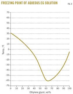
Fig. 3 presents the freezing point for an EG solution.
Plant analysis
The first step of the study was to take a sample of the lean and rich glycol streams in the process. The samples were tested for water content, glycol degradation, pH, and solids contamination. It was initially noted that the lean EG sample water content was lower than the target range. Typically, lean EG water content should be 18-25 wt % effectively to suppress the freezing point of water in the system. The Clearwater lean EG sample had a water content 15.8 wt %.
Because lean EG water content is a function of reboiler temperature, it was suggested that this possibility be addressed. Typically reboilers for an EG system are set 237-248° F. Because the Clearwater EG reboiler was running at 248° F., it was recommended to reduce this temperature slightly to allow for higher water content in the lean EG stream. This was a quick change that could be done with the plant online. Having the reboiler run too hot is a waste of energy, and it also may degrade the EG. Table 1 presents EG analysis results for 2012-13.
The second issue noted in the lean EG sample was the presence of propylene glycol (PG). About 10 wt % of the sample was PG, which in theory should not be present at all. PG in the sample indicates that the glycol purchased from a previous chemical supplier was contaminated before it entered the system. PG is counterproductive to the entire refrigeration process; it has a high affinity for hydrocarbons and will carry them into the glycol regeneration loop where they will be boiled off with the water. This can result in unnecessary hydrocarbon liquid losses.
This could have also been contributing to additional glycol losses through the still column. Because there is no way to rid the system of PG besides emptying it, it was recommended that the entire EG system be flushed and replaced with a fresh batch of 80:20 EG. A complete flush of this system was estimated to cost $5,000 (Can.). As a plant turnaround was already planned for September 2013, the timing was good for this replacement to occur.
Fig. 4 presents the plant layout with recommended injection rates.
It was also noted that the rich glycol water content was 24 wt %, when the recommended practice is 35-45 wt %. This shows the extent of the water pick-up after the glycol enters the chiller, gas-gas exchanger, and settles in the LTS. Higher water pick-up is better and is a function of glycol circulation rate. A lower glycol circulation rate allows for longer retention time in the LTS, which results in a higher water pick-up by the EG.
At the time of sampling, the glycol circulation rate at the plant was 1 gpm. The calculated required glycol circulation rate, however, based on plant conditions at the time of the study was only 0.26 gpm. The lower glycol rates increased the glycol-NGL separation time in the LTS, allowing the liquids to separate more efficiently with less NGL carryover. As a result, production went to 163 b/d from 143 b/d an increase of 14% in NGL production.
It is interesting to note that higher glycol circulation did not reduce or eliminate the freeze-ups in the LTS. The EG pump installed at site was functioning at its lowest possible rate. The recommendation was to resheave the pump and install a variable frequency drive (VFD) to allow for lower EG circulation rates. This would also reduce fuel gas use by the pump. The glycol nozzles in the gas-gas exchanger and the chiller would also need to be replaced to ensure the EG still had an effective spray pattern onto the process gas with the lower circulation rate. The cost for a VFD installation on a pump of this size as well as nozzle replacements in the gas-gas exchanger and the chiller was estimated to be about $6,000. Finally, it was recommended to discontinue methanol injection into the refrigeration process.
Because the above recommendations would optimize the glycol loop, the methanol would no longer be required as a safety net. The savings from this would be $3,000/year in methanol costs.
Implementation
Based on these recommendations, the following changes were implemented at the Clearwater plant during the plant turnaround in September 2013:
• Discontinued methanol use.
• Replaced entire EG system with new 80:20 EG.
• Installed a VFD on the EG pump.
• Changed out EG nozzles in the gas-gas exchanger and the chiller.
Implementing these changes yielded several benefits.
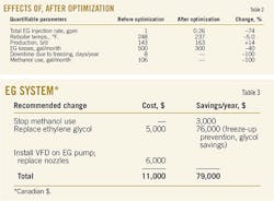
First, the Clearwater plant has experienced no freeze-ups in the LTS since modifications were made. An average of eight/year freeze-ups were occurring before these changes, which caused a loss of about 1,120 bbl/year of NGL (based on 143 b/d NGLs on average). This proves that a properly functioning EG system makes a difference. Methanol use has been discontinued and has not been required since. Table 2 presents the quantifiable parameters, before and after optimization.
All EG systems will require top-ups from time to time, as there will always be EG losses to some extent. Before these changes, it was estimated that 500 gal/month of EG were required to top up the EG system. The high circulation rate and contamination, among other factors, all contributed to unnecessary EG losses. After these changes, it was estimated that only 300 gal/month of EG were required to top up the system. This is a savings of about $1,000/month.
Table 3 outlines the simple changes that were made to the EG regeneration system and the methanol system, as well as the associated costs and savings. Because this is a small plant, the savings significantly affect the annual budget.
The Clearwater plant is a small-scale plant, but it is an effective case study to show that process monitoring and regular EG sampling are important. In many cases, small changes can be made to the EG system to increase NGL production and significantly reduce operating costs at refrigeration plants.
Based on a presentation to the Laurance Reid Gas Conditioning Conference, Norman, Okla., Feb. 22-25, 2015.
The authors
