Hydraulic analysis key to effective, low-cost demethanizer debottleneck
A hydraulic analysis successfully identified a bottleneck in a demethanizer column at Eastman Chemical Co.'s Longview, Tex., olefins plant.
Flooding, apparent just above the tower swage (where the column's diameter changes), was causing the bottleneck in Eastman's demethanizer. A simulation of plant operating data provided the basis for a detailed hydraulic analysis.
The hydraulic analysis showed no bottleneck above the swage but found a bottleneck caused by downcomer backup flooding just below the swage. It also revealed that all trays below the swage were operating close to the downcomer backup-flooding limit.
The analysis found that the root cause of downcomer backup flooding was too small open-hole areas on trays below the swage. Replacing all tray panels below the swage with new panels containing more holes increased the hole area, which completely eliminated the flooding and increased column capacity. Demonstrated capacity went up more than 20%; Eastman has not yet discovered the column's capacity limit.
After the hydraulic limitation was eliminated, the coldest tower feed drum could run at a significantly lower temperature, which reduced ethylene losses in the tower overhead.
A good understanding of the equipment limitations and a correct hydraulic analysis, combined with field measurements and simulation, was the key for successfully identifying and eliminating the tower bottleneck.
Hydraulic analysis
In the preface to a recent book, Norman Lieberman states, "the general knowledge as to how process equipment really functions is disappearing from the process industries. This is not only my opinion, but the general view of senior technical managers in many large corporations."1
A consequence is that hydraulic analyses that identify equipment bottlenecks are becoming a lost art. When a problem arises, the approach is often to replace some or all the trays with specialty trays or packing.
This "sledge-hammer" solution often, but not always, solves the problem. When successful, the bottleneck is removed using an unnecessarily expensive solution. If this solution is unsuccessful, however, the bottleneck will remain.
In one case, a feed that flashed upon entering a demethanizer downcomer bottlenecked an entire olefins plant for 17 years.2 The bottleneck survived three failed fix attempts before a good hydraulic evaluation finally led to the correct bottleneck diagnosis. Once correctly diagnosed, the bottleneck was easily and inexpensively eliminated.
This article presents the debottlenecking of three similar demethanizers. The successful debottleneck involved neither specialty trays nor packing. Instead, the process used good engineering principles to identify and diagnose the equipment bottleneck. The result was an inexpensive, successful debottleneck readily implemented during a turnaround.
A good understanding of process equipment and a correct hydraulic analysis, combined with field measurements and simulation, is the key for identifying and eliminating tower bottlenecks.
Process, bottleneck description
Eastman's Longview plant produces nearly 700,000 tonnes/year of ethylene.
In the demethanizer chiller system, cracked gas is chilled and condensed in four stages with progressively colder levels of refrigerant. Each chilling stage produces a liquid stream, which is flashed to the demethanizer pressure and fed to the tower.
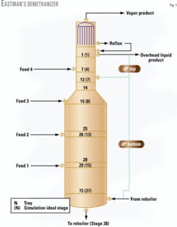
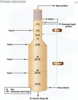
Feeds enter on Trays 7, 15, 26, and 29, with those condensed at colder stages entering progressively higher in the column. The tower has a small-diameter upper section, containing 14 sieve trays, and a larger-diameter bottom section containing 59 sieve trays.
The demethanizer (Fig. 1) separates hydrogen and methane from ethylene and heavier components. The primary objective is to minimize ethylene losses in the overhead while preventing methane from entering the bottom product.
At normal operating conditions, overhead ethylene losses are about 1.5 mole %, and methane in the bottoms product is less than 1 ppm (mole).
The tower would operate smoothly up to its bottleneck point with a normal tower differential pressure of 5-6 psi. Once the tower feed rates increased to the bottleneck point, flooding occurred in the tower's top section and the pressure drop rose to 8 psi.
With no corrective action, the pressure drop kept climbing, up to a maximum of 10-12 psi. Cutting back on the reflux helped alleviate the flooding. This decreased the pressure drop, but at the expense of more ethylene losses in the overhead.
An alternative corrective action was to increase the temperature in the drum that fed Tray 7. This lowered the feed rate to the tower's upper section and lowered the pressure drop, but again at the expense of greater ethylene losses.
The differential pressure system in Fig. 1 indicated that the increase in pressure drop occurred above the swage. The result was a bottleneck in Trays 7-14.
Because Tray 7 feed is predominantly liquid, the section between it and the swage usually bottlenecks the demethanizer's upper section. Some vendors proposed replacing Trays 7-14 with specialty high-capacity trays. Because these trays had a small, 18-in. spacing, Eastman was concerned that the tray spacing could be too small. An alternative vendor proposal was replacing the trays with random packing.
Eastman did, however, want to perform a hydraulic analysis to identify the bottleneck correctly. The first step was to prepare a simulation that reflected plant data; this simulation became the basis for the hydraulic analysis.
Feed train simulation
To determine the feed flow rates and compositions correctly, we had to simulate the feed train rigorously. We collected operating data around the feed train and demethanizer, which formed the basis for the simulation.
During the simulation's preparation, it became apparent that some of the feed train's operating data were inconsistent. Initial data collected included pressure, temperature, and liquid flow rates in and out of the feed drums.
When we matched the temperature and pressure, large discrepancies occurred between the calculated and measured flow rates. We then collected additional operating data to help resolve these inconsistencies.
We analyzed vapor samples from the feed drums and took more accurate temperature and pressure measurements. We calculated the liquid feed rates to close the material balances around individual drums. This approach resulted in a better agreement between simulated data and plant data.
Despite attempts to manipulate pressure and temperature, closure of the material balance around the flash drum feeding Tray 15 was unsuccessful. We checked the measurements and found them to be repeatable.
To close this balance, we needed to simulate 8.4% liquid entrained in the vapor leaving the drum. The material balance error around this drum indicated that either the vapor analysis from this drum was incorrect or that actual entrainment was occurring.
Tower simulation
The tower simulation was based on plant data. We used the Peng-Robinson equation of state for vapor-liquid equilibrium (VLE) prediction, which is common practice for demethanizers.
We could have improved the VLE accuracy by tuning the equation closely to match VLE data, as in a previous analysis.3 In the previous analysis, however, the objective was correctly to predict separation and efficiency, which requires accurate VLE predictions. In this case, the objective was to develop vapor and liquid loads for a hydraulic analysis; we felt that the version in the commercial simulator was adequate for this purpose.
Due to uncertainties in the reflux flow measurements, it was difficult to calculate an overall column efficiency reliably. Based on experience with columns in similar service, we selected a 50% overall column efficiency. This gave us an excellent match to product compositions and was therefore used in the subsequent column simulation.
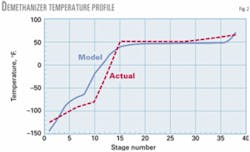
Fig. 2 compares a simulated temperature profile to actual plant data. There was a good match from near equilibrium in Stage 15 to the column's base.
Above Stage 15, there was a significant discrepancy between simulated and measured temperatures. This discrepancy reflected a combination of sampling and measurement errors and modeling deficiencies.
Attempts to alter simulation conditions to obtain a temperature match in the top 15 stages wreaked havoc with the rest of the profile and were therefore abandoned. Mitigating the discrepancy would require a time-consuming and costly detailed analysis, both of the simulation input data and field measurements.
We examined the sensitivity of the hydraulic loads to variations in the temperature profile by varying simulation conditions; the effect was minimal. We therefore concluded that the benefits of perfecting the simulation model for the hydraulic study did not justify the cost.
We did, however, follow one lead. Fig. 2 shows that measured temperatures were lower than simulated temperatures at the tower's cold end, which was unexpected.
In cryogenic services, freeze-ups at thermowells often produce false high measurements; measured temperatures tend to be higher than simulated. This fact implied that we did not have a measurement problem; it was possible that the upper feeds in the simulation were richer in high-boilers than the actual plant.
To reduce the feed's boiling points, we lowered the simulated temperatures of the two coldest feed drums. When the temperatures in both drums were lowered 20° F., the simulated temperature profile perfectly matched the plant data.
Subsequent hydraulic studies for both alternate versions of the simulation led to negligible differences in the hydraulic results. The hydraulic analysis and our conclusions, therefore, were insensitive to even the large difference between the two models.
Graphical analysis
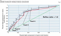
Fig. 3 is a Hengstebeck diagram—a McCabe-Thiele analysis modified for multicomponent systems.4 It has been advocated as a valuable tool for troubleshooting tower simulations and gaining insight into tower operations.5
Fig. 3 shows that the column is close to a pinch near Stage 6. The operating reflux ratio of 1.0 was therefore close to minimum reflux. The proximity to the pinch and minimum reflux fully explained why ethylene losses in the tower overhead vapor rapidly escalated when the reflux rate was reduced (in an attempt to stop flooding).
It similarly explained why warming up the coldest feed drum (also in an attempt to stop flooding) also rapidly raised ethylene losses. Finally, it explained why the initiation of flooding was not accompanied by a rapid rise in ethylene losses, at least initially.
Reflux, not trays, was in short supply; therefore, losing mass transfer on some trays caused less ethylene loss than a reflux rate cutback.
Fig. 3 also shows how one can optimize the tower operation. The key is the liquid-vapor ratio just above the pinch point. Liquid to this region comes from the reflux and the upper feed. One can balance the two flows to optimize either ethylene recovery or ethylene refrigerant consumption.
A maximum reflux and minimum temperature in the upper flash drum minimizes ethylene losses. To minimize the load on the refrigeration compressor, the upper feed drum must still be as cold as possible, but a reduced reflux (which is condensed using colder refrigerant) can lessen the load on the ethylene refrigeration system. A rapid escalation in ethylene losses in the demethanizer overhead constrains this reflux reduction.
Hydraulic analysis
The simulation supplied vapor and liquid loads and physical properties, which served as the basis for our hydraulic analysis. The hydraulic analysis used Fractionation Research Inc.'s (FRI) correlations and data.
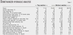
Table 1 summarizes key tray dimensions and results of our hydraulic analysis. It shows that the tray dimensions vary from one tower section to another, probably tailored to the tower initial design loads.
Table 1 shows that none of the trays operated anywhere near jet flood. This is not surprising because vapor densities in high-pressure demethanizers are usually high, which reduces vapor velocities and keeps most demethanizers well away from jet flood.
Table 1 also shows that none of the trays operated close to the downcomer-choke inlet velocity, which is a common limit encountered in high-pressure demethanizers. The comfortable margin is due to the large downcomers in the bottom section, which are optimized to circumvent this limit.
Table 1 shows that the downcomers of the trays below the swage had extremely high froths. The results for downcomer backup were directly calculated from an FRI correlation.
Calculations indicated that Trays 15 and 25 were operating above the downcomer backup-flood point. Below Tray 25, the column was near the downcomer backup-flood point. Above the swage, Trays 1 to 14 operated at a safe margin from the downcomer flood limit.
Our investigation focused on the root cause of the high downcomer froth backup. On Tray 20, the downcomer length, from the floor to the top of the outlet weir above, was 19.5 in. The calculated froth height was 20.6 in.
The calculated aeration factor was 0.574, which is similar to, or slightly higher than, aeration factors typical for this type of system.6 The clear liquid backup in the downcomer was therefore 11.8 in., which is extremely high for trays with an 18-in. spacing.
The backup was the sum of the inlet clear liquid height on the tray (calculated at a normal 3.1 in.), the head loss of liquid exiting the downcomer (calculated at a normal 1.2 in.), and the tray pressure drop, which was an extremely high 7.5 in.
The root cause of the high pressure drop was an extremely high "dry" pressure drop, i.e., friction through the sieve holes. FRI's correlation gave an extremely high dry-tray pressure drop of 6.4 in. of liquid, suggesting shortage of hole area on the tray.
Table 1 shows that on Trays 15-25, the tray hole area was only 3.2% of the active area. This hole area is small compared to normal trays, which typically have a hole area 8-10% of the active area.
Furthermore, the trays have large downcomers, which makes the active areas quite small, about 40% of the tower cross-sectional area. This small hole area, coupled with large downcomers, created a large dry-tray pressure drop, raised downcomer backup, and initiated tower flooding.
The dry-tray pressure drop below Tray 25 was still high, but to a lesser extent. On these trays, the larger hole areas somewhat reduced the dry pressure drop, but it was counterbalanced by the high liquid loads and taller weirs that raised the tray inlet clear liquid heights and liquid head pressure drop. On these trays, the taller tray spacing kept the downcomer froth backup some margin away from flood.
The hydraulic analysis showed that the tower bottleneck was not on Trays 7-14 as we initially thought. These trays operated a large margin away from any type of flood. Instead, the flood initiated in the section just below. Because the bottleneck occurred near the top of the section below, it appeared identical to flood initiating in the section above.
A search of historical data did not show why the trays below the swage had small hole areas. It is likely that, in the initial years, the plant and tower operated at much lower loads.
A common practice for dealing with low tower loads is to reduce sieve hole area. This prevents tray weeping and permits sieve trays to achieve good efficiencies at high turndown. Since then, tower plant throughput increased significantly, raising the hydraulic loads. Turndown was not a major issue, but the small hole area became a bottleneck.
Feed distribution piping
Any tower hydraulic analysis is incomplete until all the relevant points of transition (i.e., any point where a stream enters or leaves the tower) are complete. Our survey of tower failures indicated that points of transition are some of the most severe tower bottlenecks.7
A different demethanizer experienced a bottleneck due to flashing feed entering a downcomer.2 It was therefore imperative to analyze all the transition points where the flooding initiated. Our analysis of the feed piping indicated that internal piping was well designed for a potentially flashing feed service and would not contribute to the column bottleneck.
Solution
The decks of Trays 15-73 were replaced with new sieve decks that had more hole areas. The new hole areas were increased to the point of incipient weep and ranged from 8.5% on Trays 15-25 to 12% of the active areas on Trays 29-73. The downcomers were not modified.
The calculated froth in the downcomers was lowered to 63-71% from 87-106% (Table 2).
After the retray, tower flooding and bottleneck completely disappeared. The demonstrated tower capacity increased more than 20%. Pressure drop across the tower declined to 3 psi.
Eastman has encountered no capacity limit in the tower since the debottleneck. The cost of replacing the sieve decks was small.
Eastman operates two other plants with similar demethanizers. The analysis described here extended to those plants as well. The demethanizers in the other two plants were debottlenecked using a similar solution, with the same results.
Even though the bottleneck appeared to occur on Trays 7-14, it initiated in a lower section. Replacing Trays 7-14 with specialty trays or packings, as proposed by some vendors, would therefore have done nothing to alleviate the tower bottleneck.
It took a good understanding of the equipment limitations and a correct hydraulic analysis, combined with field measurements and simulation, to identify and diagnose the bottleneck correctly. This effort was rewarded by an effective, low-cost solution.
References
1.Lieberman, N.P., and Lieberman, E.T., "A Working Guide to Process Equipment," New York: McGraw-Hill Cos., 1997.
2.Kister, H.Z., Hower, T.C., de Melo Freitas, P.R., and Souza Neto, J.N., "Problems and Solutions in Demethanizers and C2 Splitters with Interreboilers," presented to the 8th Annual Ethylene Producers Conference, AIChE Spring National Meeting, New Orleans, Feb. 25-29, 1996.
3.Kister, H.Z., Chellappan, S.G., and Spivey, C.E., "Debottleneck and Performance of a Packed Demethanizer," presented to the 4th Annual Ethylene Producers Conference, AIChE Spring National Meeting, New Orleans, Mar. 28-Apr. 1, 1992.
4.Hengstebeck, R.J., "An Improved Shortcut for Calculating Difficult Multicomponent Distillations," Chemical Engineering, Jan. 13, 1969, p. 115.
5.Kister, H.Z., "Troubleshooting Distillation Simulations," Chemical Engineering Progress, June 1995, p. 63.
6.Kister, H.Z., "Distillation Design," New York: McGraw-Hill Cos., 1992.
7.Kister, H.Z., "What Caused Tower Malfunctions in the Past 50 Years?," IChemE Transactions, January 2003, p. 5.
The authors
Steven P. Bellner([email protected]) is a principal chemical engineer for the Voridian Division of Eastman Chemical Co., Kingsport, Tenn. He has more than 19 years' experience in process synthesis and plant design, specializing in all aspects of process simulation. Bellner holds a BS in chemical engineering from the University of Texas at Austin. He is a registered professional engineer in Texas.
Bill Ege([email protected]) is an engineering associate at Eastman Chemical Co., Longview, Tex. He has 30 years' experience in the process design of chemical plants, all of it with Eastman. Ege holds a BS in chemical engineering from the University of Kansas and an MBA from Stephen F. Austin State University, Nacogdoches, Tex.
Henry Z. Kister ([email protected]) is a senior fellow and director of fractionation technology at Fluor Corp., Aliso Viejo, Calif. He has 30 years' experience in design, troubleshooting, revamping, field consulting, control, and start up of fractionation processes and equipment. Previously, Kister was a staff consultant on distillation for Brown & Root Corp. and also worked for ICI Australia and Fractionation Research Inc. (FRI). Kister holds a BE and ME in chemical engineering from the University of NSW, Australia. He is a fellow of IChemE, a member of the AIChE, and serves on FRI's technical advisory and design practices committees.
