Supersonic nozzle efficiently separates natural gas components
A new technology based on the adiabatic cooling of swirling gas flow in a supersonic nozzle is effective in separating and processing natural gas components.
A pilot test facility in Alberta, Canada, has shown that the 3-S separation device uses 10-20% less compressor power than plants that use a Joule-Thomson valve or turboexpander, based on the same extraction level.
Potential applications for 3-S separators in gas processing plants include:
• Gas preparation for transportation.
• LPG extraction, shallow cut, and deep cut.
• Offshore gas separation and treatment facilities.
• CO2 extraction, ethane recovery, and LNG applications.
3-S separators provide a cost-effective and highly efficient extraction process for C3+ gas components combined with a potential reduction in energy consumption.
Laval nozzle
Existing approaches to obtaining low temperatures are based on the Joule-Thomson effect and use of gas-expansion equipment. The gas processing industry developed and has used them extensively.
Recent research has produced new technologies based on adiabatic cooling, which results from gas expansion in a supersonic nozzle. Cryogenic temperatures result because part of gas enthalpy transforms to kinetic energy, which can be reused to increase the pressure in the system of supersonic and subsonic diffusers.
The nozzle’s working section liquefies target components. It experiences significantly lower pressures and temperatures than would occur at the facility exit without the addition of external energy.
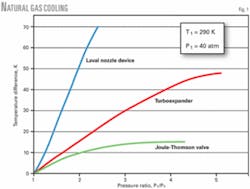
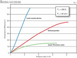
Fig. 1 compares the degree of natural gas cooling at the same differential pressure for a Joule-Thomson valve, turboexpander, and the new device that uses a Laval nozzle.
For the Laval nozzle, we assume that ΔT = ΔTst= T1 - Tst, where T1 is the input gas temperature and Tst is the static temperature of gas after its expansion. The output pressure, P2, after flowing through the system of diffusers is assumed to be two times smaller than a respective pressure P2 in supersonic wind tunnels at the same Mach number.
Fig.1 shows that natural gas expansion in the Laval nozzles and subsequent pressure increase in the system of diffusers allow one to obtain a ΔTst that exceeds the temperature difference ΔT in expanders at the same differential pressure.
Supersonic separation technologies
The supersonic nozzle separates drops of condensed liquid using centrifugal forces, which are formed by two different methods. The swirling (twisting) device can be at the outlet of the supersonic nozzle or the gas flow is swirled in the plenum chamber ahead of the supersonic nozzle.
Twister BV, Rijswijk, Netherlands, has developed a product that uses the first method.1 2 A wing or blade at the end of the nozzle in the supersonic flow zone immediately before the liquid extraction device provides swirling to the gas passing through the device. The Twister separator dehydrates gas and separates heavy hydrocarbons.
This approach to create flow swirling forms a shock wave that heats the gas, creates pressure losses, and creates subsonic flow zones in the separation area. As the flow decelerates, the shock wave produces partial crushing and evaporation of the drops of liquid.
The second method, using a swirling device in the plenum chamber ahead of the nozzle, was independently proposed by a group of Russian specialists and developed with their participation by TransLang Technologies Ltd., Calgary.
This method initiates gas swirling in the plenum chamber so that the tangential velocities, when combined with the centrifugal forces, separate any liquid drops formed in the supersonic nozzle and deliver them to a special extracting device.
This approach minimizes total pressure losses in the shock waves and separates the flow deceleration zone behind the shock wave from the drop separation zone.
This method of flow swirling is called 3-S technology (supersonic separation) and the devices designed with this technology are called 3-S separators.3 4
Fig. 2 shows a 3-S separator.
Its distinctive feature is the arrangement of the swirling device in the plenum chamber. This is followed by the supersonic nozzle, the working section, the device for separating two-phase flow with liquefied components, the supersonic and subsonic diffusers, and finally the directing vanes.
Different types of devices are used to achieve flow swirling that gives a centrifugal force with an acceleration of about 106 m/sec2 in the supersonic nozzle and the working section. The devices include blades on the central body and one or more gas jets along the tangent to the surface of the nozzle entry section. These options allow optimal design for this section of the device.
3-S technology studies
3-S separators have been studied and tested since 1996. Experimental laboratories were constructed to fully analyze the process of drop formation in supersonic flows. In addition to the pattern of swirling supersonic flows, researchers determined drop distribution functions along the nozzle radius and length, and also developed optical methods to measure drop sizes.
Chromatographic procedures were modified to apply to experimental conditions. The calculation programs for swirling natural gas flows in supersonic nozzles were elaborated to give due recognition to actual gas properties and phase transitions.
The desire to optimize the design for industrial 3-S separator applications led to construction in Russia of an experimental test plant providing natural gas flow rates of 1.2-2.5 kg/sec at the plenum chamber entry with pressures up to 75 atm. The temperature of gas varied from 20° to -60° C. with an exhaust pressure of 15-60 atm.
The test plant can measure gas flow rates at different points in the 3-S device, pressures along the entire gas flow path channel, and gas temperatures in different parts of the test device. Furthermore, it allows chromatographic analyses of gas composition. The test plant is equipped with special devices to supply a specified gas composition.
Target component removal determines the 3-S separator’s effectiveness. Currently more than 400 test runs in this test plant have investigated the operation of various design versions of the 3-S separator and its components.
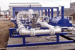
The next stage included the design and manufacture of a pilot plant with a greater natural gas flow rate, up to 12 kg/sec, at an inlet pressure of 50-70 atm. This plant, designed for extended periods of service was built in Calgary (Fig. 3).
A range of experimental investigations was conducted up to those approaching industrial applications. Experimental results confirmed the preliminary results and conclusions from the laboratory test device.
The first industrial 3-S device has recently started operating at a gas-treatment plant in Western Siberia.
From the data obtained from these test facilities, mathematical programs were developed to calculate the 3-S separator physical components under different operating conditions.
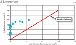
Fig. 4 shows the results of a series of test runs carried out in the pilot plant at a gas flow rate of 1.5-2.5 kg/sec. The separation effectiveness for heavier components in the 3-S separator is plotted on the vertical axis and the effectiveness of the Joule-Thomson valve is on the horizontal axis.
The separation effectiveness is measured with Δa = a0 − a, where a0 and a are the initial and final mole concentrations of components.
The tests used different feed component concentrations, entry-gas pressures and temperatures, differential pressures, and gas dynamic flow conditions. The results are for Mach numbers less than 1.5 in the 3-S separator working section.
The separation efficiency in the 3-S separator slightly decreases with an increase of heavy components. This is due to the characteristics of thermodynamic expansion of mixtures with high concentrations of heavy components; for these types of mixtures, the appearance of liquid in the separator premix chamber is normal.
For certain conditions, especially with small concentrations of heavier hydrocarbons, the 3-S separator can separate liquid components that a Joule-Thomson valve could not.
Comparison with existing technologies
At the same differential pressure, the 3-S separator can achieve considerably lower temperatures in the liquid separation section due to adiabatic cooling during expansion in the supersonic nozzle and the Joule-Thomson effect.
We compared the effectiveness of the 3-S separator, Joule-Thomson valve, and turboexpander in extracting C3+ from natural gas.
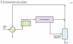
Fig. 5 shows a diagram of a facility with 3-S separator and the chiller to extract C3+ from natural gas. In this facility, natural gas is supplied to the 3-S separator after cooling in the recuperative heat exchanger and evaporator.
Gas from the 3-S separator flows to the recuperative heat exchanger, which cools the feed gas. Two-phase flow from the 3-S separator flows to the secondary separator, the gas phase of which mixes with purified flow from the 3-S separator.
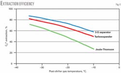
Fig. 6 shows the extraction of C3+ from natural gas and its dependence on the stream temperature after the evaporator. The feed gas temperature was 20° C. and the feed gas composition was methane, 90 mole %; ethane, 2 mole %; propane, 4 mole %; and butanes, 4 mole %.
The gas pressure at the entry and exit was 60 atm and 45 atm, respectively. Projected flow separation in the 3-S separator was based on the experimental data obtained during the tests of pilot industrial 3-S separators.
Fig. 6 also shows C3+ extraction for a Joule-Thomson valve or turboexpander.
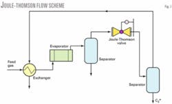
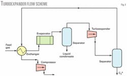
Figs. 7 and 8 show flow schemes for a Joule-Thomson valve and turboexpander, respectively.
Fig. 6 assumes that the isentropic turbine efficiency is 80% and the isentropic turboexpander compressor efficiency is 75%. Pressure losses, temperature approaches, and pressure losses in the recuperative heat exchanger are the same for all schemes.
The 3-S separator results in a higher extraction of C3+ vs. the Joule-Thomson valve and turboexpander. The 3-S separator is simpler to design, operate, and maintain.
Advantages in field plants
Gas processing plants with the 3-S separator have:
• Fewer compressor station power requirements.
• Lower pressure loss.
• Greater recovery given the same operating parameters.
• A simpler plant design.
• Fewer moving parts.
• Ease of construction and reduction in plant weight.
• Lower equipment, operating, and maintenance costs.
Calculations based on experimental data for particular fields show that using the 3-S technology results in a 30% increase in the recovery of heavier gas components for the same power requirements. For the same extraction level, the power requirement could be reduced 50-70%.
Using 3-S separators instead of Joule-Thomson valves in existing gas processing and extraction plants increases LPG extraction 10-20% with the same compressor power. For the same extraction level, it is possible to decrease the required compressor power by 10-20%.
At gas processing plants equipped with turboexpanders and coolers, using 3-S extractors could lead to a 15-20% reduction in the required compressor power at the same extraction level.
Offshore example
Because the 3-S technology has a small footprint, has no moving parts, needs no maintenance personnel, and uses the gas formation’s energy, the capital and operating costs are lower vs. conventional gas processing plants.
These factors make the 3-S technology especially promising for offshore fields. Most gas production platforms limit the gas pressure to 100 atm for safety reasons. Wellhead gas pressures often exceed 100 atm, which results in the need for a Joule-Thomson valve to reduce the gas pressure.
Replacing the Joule-Thomson valve with a 3-S separator solves several problems: pressure reduction, gas dehydration, LPG extraction, and dewpoint control.
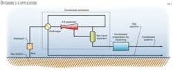
Fig. 9 shows a possible scheme using a 3-S separator for LPG extraction in an offshore gas field.
Gas from the well, after passing the wellhead, flows to the processing facility with the 3-S separator mounted near the wellhead. The facility consists of a recuperative heat exchanger, a 3-S separator, and a secondary separator.
The liquid mixture of hydrocarbons and water separated from the natural gas flow to a special facility to prepare condensate for transportation. The effectiveness of the separation process is comparable with schemes that use a turboexpander. ✦
References
1. Cottrll, A. “Technique puts gas treatment in a spin,” Upstream, Mar. 19, 2004, p. 48.
2. Okimoto, F., and Brouwer, J., “Supersonic gas condition,” World Oil, August 2002.
3. Alferov, V.I., et al., “Method and apparatus for liquefying a gas,” European Patent, EP1131588.
4. Alferov, V.I., et al., “Method of and apparatus for the separation of components of gas mixtures and liquefaction of a gas,” US Patent 6372019.
The authors
Vadim Alfyorov ([email protected]) is a director of TransLang Technologies Ltd., Moscow. He is also division head of the Central Aerohydrodynamic Institute, where he has worked since 1958. Since 1987, Alfyorov has served as a professor at the department of Flying Machines of the Moscow Institute of Physics and Technology. He holds a degree (1957) and a PhD in physics from the Moscow Institute of Physics and Technology. He is a member of the American Institute of Aeronautics and Astronautics and is an Honoured Scientist of the Russian Federation.
Lev Bagirov ([email protected]) is a director of TransLang Technologies Ltd., Moscow. He has also been a director of new technologies for the ENGO Research Center since 1998. Before that, Bagirov served as a senior scientist in the Institute for Problems in Mechanics, Russian Academy of Sciences. He holds a degree (1966) and a PhD in mathematics (1970) from Moscow State University.
Leonard Dmitriev is a chief engineer for TransLang Technologies Ltd. and senior research scientist at the Central Aerohydrodynamic Institute, Moscow, specializing in applied aspects of gas dynamics. He has worked at the institute since 1964. Dmitriev holds a degree (1963) in physics from the Moscow Institute of Physics and Technology.
Vladimir Feygin ([email protected]) is a director of TransLang Technologies Ltd., Moscow. He has also served as an executive director of ENGO Research Center since 1990. In 1970-2004, Feygin was a researcher at Gazprom’s institute, Niigazekonomika. He holds a degree (1967) and a PhD (1971) in mathematics from Moscow State University.
Salavat Imaev ([email protected]) is deputy director of the fundamental aspects of oil and gas science and technology department at the Moscow Institute of Physics and Technology. He holds a degree (1993) and a PhD (1998) in physics and mathematics from the Moscow Institute of Physics and Technology.
John R. Lacey ([email protected]) is president of of John R. Lacey International Ltd. and chairman of TransLang Technologies Ltd., Calgary. He has advised on major oil and gas developments and transmission projects around the world. Before forming his own company in 1970, Lacey worked for BP Canada for 15 years. He holds a BSc (1953) in petroleum technology from the Royal School of Mines, London, and a PhD (1955) in geology from the University of London. Lacey was elected to the Russian Academy of Natural Sciences in 1996 and is Honourary Consul-General for the Kingdom of Thailand.
