Simulation study determines optimum turboexpander process for NGL recovery
Simulation of NGL recovery from natural gas streams of wide compositions and for different turboexpander process configurations has revealed that the gas-liquid subcooled process (GLSP) yielded an overall average ethane recovery of about 80% and, in the case of a location with variable feed compositions, GLSP would yield the highest average ethane recovery.
The study also showed that the gas-subcooled process (GSP) exhibited the highest C2 recovery for medium composition of C2+. The study also showed that the relative amount of heavy component in the feed stream determines which cryogenic process configuration should be chosen.
The other two processes tested were a Basic process and a liquid subcooled (LSP) process.
For all configurations, ethane recoveries reached no less than 74%.
The study used Hyprotech’s HYSYS process simulation software.
Feed compositions
The composition of natural gas is important in a decision about what process configuration to employ for NGL. This study, therefore, tested natural gases of wide-ranging compositions available both in the literature and at three gas fields in Saudi Arabia for the different turboexpander process configurations. These configurations are based on energy integration of the processes.
With a worldwide drive towards increasing the use of natural gas has come the need to minimize energy consumption associated with the chosen process. An important requirement in natural gas processing is that the process be flexible to accommodate a range of natural gas compositions.
The process choice is also guided by the cyclical nature of the market preference for ethane and propane. Traditionally, the ethane-plus richness determines the type of the process to be employed.
NGL may be recovered by many methods, among which are compression, straight refrigeration, cascade absorption, ambient temperature absorption, adsorption, Joule-Thomson expansion, and expander.
Lean natural gas usually is processed by a cryogenic turboexpander (TE) process, while rich gas is separated with a noncryogenic adsorption process.
The TE process has decided advantages over adsorption for processing lean gas. TE may be combined with J-T valve and external refrigeration. The combination is necessary to improve the energy efficiency or to obtain greater recoveries.
For a middle-of-the-road gas composition the choice becomes more challenging. A recent report has shown that the adsorption process has a 32% lower cost than the gas-subcooled version of the turboexpander process for processing a middle-of-the-road composition.1
The present study conducted different process configuration strategies for gas processing based on the TE using a natural gas of C2+ composition range of 16-72% for the analysis.
The study employed the HYSIS simulation software for the study to establish the optimal TE process configuration for natural gas of wide-range composition.
Process description
TE plants are often used for the recovery of lighter gases (methane, ethane) from natural gas streams. Cooling natural gas to extremely low temperatures through a network of heat exchangers and valves results in partial liquefaction of the stream and enhances ethane recovery. A low-temperature separator (LTS) then separates the cold liquid and vapor.
The liquid stream from LTS is flashed across a J-T valve (in most TE processes) for additional chilling. The J-T effect is the cooling that occurs when a highly compressed gas is allowed to expand in such a way that no external work is done.
Expanders are applied at lowest temperature levels of configurations because this is where they are thermodynamically more efficient.2 3 Therefore, vapor from the LTS flows into the expander unit where the process temperature is further reduced and also work is produced, which is utilized for recompression.
The liquid product of the expander and the valve outlet both feed to the demethanizer tower. Heat integration allows for precooling of the hot feed, which is thermodynamically more efficient.
This approach is used in this design to prechill the feed to the LTS by use of the demethanizer overhead stream and side reboilers.
Building the model
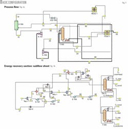
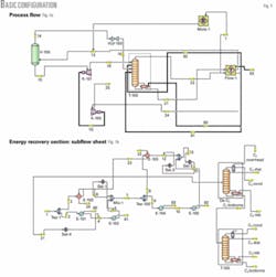
All models were designed with the HHP simulation software. Fig. 1a shows a flow sheet for one of the configurations (Basic process). The figure has one separator (V-100), one demethanizer (T-100), expander (K-101), compressor (K-100), and a J-T valve (VLV-100).
The simulation employed the Peng Robinson thermodynamic property package, which is adequate for the composition investigated.4 Much of the chilling section is shown as a subflow sheet (FLOW-1) with a cascade of heat exchangers that use the duties (81 and 82) from the column, as shown in Fig. 1b. This is where all the heat integration and recoveries are done.
The exchanger network was built as a subflow sheet. A special feature of the HHP simulation software in the subflow sheet environment connected the main flow sheet to the subflow sheet (Fig. 1b).
Different configurations of the expander process were used to achieve the production of NGL and the results were compared. These configurations were further studied with modification for the downstream separation of ethane and propane. The following paragraphs discuss these configurations.
• Basic: one-stage separator process. Fig. 1a shows flow sheet for one of the configurations (Basic process). The figure has one separator, demethanizer, expander, compressor, and J-T valve. Much of the chilling section is shown as a subflow sheet (Flow-1) with a cascade of heat exchangers using the duties (stream numbers 81 and 82) from the column, as shown in Fig. 1b.
This is where all the heat integration and recoveries occur. The exchanger network was built as a subflow sheet. A special feature of HHP in the subflow sheet environment was used to connect the main flow sheet to the subflow sheet (Fig. 1b).
• Gas subcooled process. In GSP, gas from the main demethanizer column is used for precooling. The feed gas that goes into the LTS is precooled through a series of external refrigeration using heat exchangers E-101 to E-105. The colder gas is flashed in the separator to produce a gaseous overhead product and a liquid bottom product. Part of the overhead gas then flows to be cooled by the demethanizer overhead.
By this process the gas is condensed and subcooled before being flashed into the top of the demethanizer. This process provides a cold top stream rich in heavier hydrocarbons.
The other part of the overhead gas stream enters the expander. It operates isentropically and lowers the feed pressure. More horsepower is recovered through the expansion process and thus reduces or compensates for the energy requirement in the compressor.
Expansion efficiency is a function of temperature. Therefore, the inlet temperature to the expander is critical to the determination of the expander performance. The outlet of the expander is then routed to the middle of the column. The separator liquid is also flashed through a J-T valve into the demethanizer column at an intermediate feed point.
• Liquid subcooled process. In LSP, the liquid from the LTS containing most of the heavier hydrocarbons is subcooled and split into two. After the split, the first part is flashed through a J-T valve for further cooling before entering the demethanizer at the top of the column. The other part is also flashed and returned against the separator liquid.
This part then goes through a second J-T valve before entering the demethanizer column at a lower point. This alternate design offers further reduction in energy consumption. It also provides cold heavy hydrocarbon top feed that will act as scrubber for the incoming gas. The gaseous overhead flows to the expander after which it is fed at the intermediate part of the demethanizer.
• Gas liquid subcooled process. GLSP combines the expected advantages of GSP and LSP mentioned previously. In this process the liquid from the low-temperature separator is precooled before it is split into two.
The first part goes through a J-T expansion to be cooled further before entering the middle part of the column. The other part is expanded and returned against the liquid from the LTS that is desired to be cooled.
The gas part of the LTS is again split into two. One part is cooled by the sales gas of the demethanizer. The other part of the gas from the LTS then goes through expander K-101 for further cooling before entering the demethanizer at the top of the column.
Results
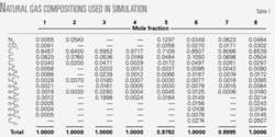
Table 1 shows the compositions of the inlet gases used for the study. The eight gas types were based on the typical compositions from various sources of natural gas.5-9 The gas composition is important in determining the type of separation process to be employed. Gases found in the Arabian Gulf region, for instance, are richer in heavier components than those in North America. Gases that have the so-called middle-of-the-road composition need to be studied carefully to determine the most beneficial configuration for NGL recovery.
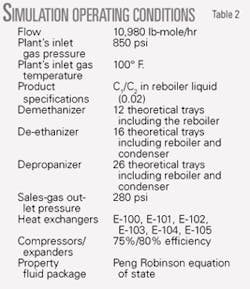
To assess the relative advantage of the alternatives, the study made various runs under different configurations and compositions at operating conditions shown in Table 2. The ethane recoveries achieved, the load on the compressor/expander, the reboiler energies, are all parameters that not only represent a significant part of the capital requirement but also indicate the energy utilization within the facility.
The study generated more than fifty runs; the figures show summaries of the results. Emphasis has been laid on energy values and ethane recoveries from demethanizer (with increasing amounts of C2+ components in a particular gas stream). For each of the process configurations HHP simulation software runs were carried out for all eight compositions.
Fig. 1 shows the Basic configurations as described previously. In Fig. 1a, the main energy recovery is from the expander, which is then utilized in the sales-gas compression. Fig. 1b shows the streams’ integration made to recover energy from the process gas, which is then utilized in the column.
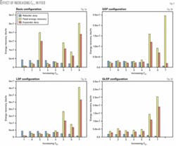
As these parameters change so do the quantities of recoverable NGL. Fig. 2 shows the reboiler duties, feed energy recoveries, and expander duties, respectively numbered as 80, 81, and 70 in the configurations.
For the Basic configuration (Fig. 1), the energies show no clear trend with increase in C2+ in the feed stream. The subcooling of the feed stream, with either gas or liquid, is higher for rich natural gas. Among the configurations, LSP (Fig. 2c) shows the highest energy recovery.
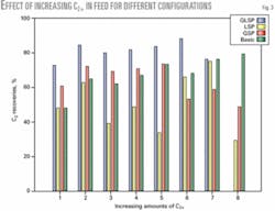
Fig. 3 shows the C2 recoveries for the configurations with increasing amounts of C2+ in the feed stream. For the Basic configuration, recovery was as high as 80% for the feed with the highest amount of C2+. It appears that the higher the C2+, the higher the recovery. This is not the case for GSP in which the highest recovery is just about 70%. The highest C2 recovery occurred when the feed had a medium amount C2+. The LSP shows lower recoveries than the Basic and GSP.
GLSP shows the highest average recoveries among all of the configurations when a combined configuration is used. Regardless of the nature of the feed, the GLSP shows highest C2 recovery, as shown in the figure. ✦
References
1. Mehra, Y.R., Saudi Aramco Journal of Technology, Spring 2002, pp. 50-56.
2. Fermandez, L., Bandoni, J.A., Eliceche, A.M., and Brignole, E.A., “Optimization of ethane extracting plants from natural gas containing carbon dioxide,” Gas Separation and Purification, 1991, 229-234.
3. Diaz, M.S., Serani, A., Bandoni, J.A., and Brignole, E.A., “Automatic Design and Optimization of Natural Gas Plants,” Ind. Eng. Chem. Res., 1997, Vol. 36, pp. 2715-2724.
4. Hysys. Process Steady State Manual, Hyprotech Corp. Canada.
5. Mota, J.P.B., “Impact of Gas Composition on Natural Gas Storage by Adsorption,” AICHE Journal, Vol. 5 (May 1999), No. 5, pp. 986-996.
6. Katz, D.L., Cornell, D., et al., Handbook of Natural Gas Engineering, 1959.
7. Snow, N., The Oil Daily, Mar. 23, 1987, p. 6.
8. Fakeeha, A.H., Journal of King Saud University, Vol. 11, Engr. Sci. (special issue), pp. 1-161 (Arabic), Riyadh (A.H. 1419/1999).
9. Gulf Cooperation Council, Economic Bulletin for GCC, No. 12, 1997.
Based on initial publication in Saudi Aramco Journal of Technology, December 2005.
The authors
Baba El-Yakubu Jibril ([email protected]) is on the faculty of the chemical engineering department, College of Engineering, at King Saud University, Riyadh.
Biographies of remaining coauthors were unavailable.
