Refrigeration provides economic process for recovering NGL from CO2-EOR recycle gas
Removing and selling NGL from the produced gas stream is one on the ways CO2 enhanced oil recovery projects can improve their economics.
These projects involve gas recycling into the reservoir for maintaining pressure and improving oil mobility. The recycled gas absorbs NGL in the reservoir that can be recovered with a refrigeration process.
The process involves refrigerating the gas and then separating, stabilizing, and recovering the NGL. A company then can market the recovered NGL as C3, C3+, C4, and C5+ or use it to spike the crude.
This article describes the following aspects of NGL recovery:
• Process plant required for each alternative (C3+, fractionated liquids, or crude spiking).
• Liquid recoveries for varying process conditions such as chiller final temperature.
• Process property method selection.
• Process flow diagram with material balance.
• Approximate costs for different process alternatives.
• Economics of the alternatives.
It is best to install this NGL recovery and refrigeration facility early in the CO2 injection project's life.
Process facility
A typical CO2-EOR NGL recovery plant consists of the basic battery with additional equipment to handle increased produced gas and water, as follows:
• Inlet separation.
• Treating or emulsion breaking for further phase separation.
• Liquid products storage (oil and water).
• Produced gas compression for all oil and water separation pressures.
• Water injection.
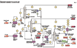
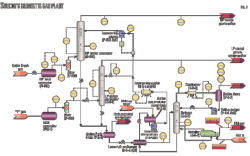
Fig. 1 shows the process flow diagram and Table 1 the material balance for 14 of the most relevant streams. The additional units for CO2-EOR include:
• Solution gas, gas-gas precooling exchanger.
• Solution gas chiller with propane refrigeration plant.
• Low-temperature separator to feed refrigerated liquids to the fractionation plant.
• Amine or mol-sieve liquid NGL sweetening unit.
• Lean-gas, pump-suction exchangers. The case shown in Fig. 1 has two 1.70 million cu m/day (60 MMscfd) trains.
• Two compressor trains of 1.70 million cu m/day each to boost the pressure from 1,256 kPa-g (182 psig) to obtain a dense phase for 92% CO2 gas. The critical point is 7,500 kPa-g (1,090 psig), and the pressure selected was 8,860 kPa-g (1,285 psig), which is in the dense-phase region. Fig. 2 shows the phase envelope for the solution gas.
• Two centrifugal multiphase pumps, one per train to boost the pressure to the injection pressure of 15,400 kPa-g, or 2,230 psig.
The analysis looked at the following three alternatives for liquids recovery:
1. Fractionation plant with de-ethanizer, depropanizer (sell C3 product), debutanizer (sell C4 and C5+ product), and distillation towers with ancillaries (aerial condensers, reflux drums reboilers, and product coolers).
2. De-ethanizer to produce C3+ product and sell.
3. De-ethanizer to produce C3+ and spike the crude.
Process design
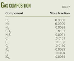
The design assumed a gas with a 1.5 sp gr (43.6 molecular weight). Table 2 shows the gas composition.
This article presents the design for only the 92% CO2 gas content with a full fractionation case because the recoveries for this case are more conservative due to the high CO2 concentration. The base case includes a fractionation train because all other alternatives are subsets of it. The other two alternatives either sell or spike the crude with the C3+.
The analysis used the Peng-Robinson property method for all the simulations.
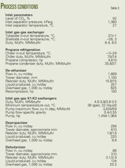
Table 3 summarizes the key stream simulations of the process shown in Fig. 1.
Propane refrigeration
The refrigeration loop is in the upper right-hand corner of Fig. 1. A gas-gas exchanger precools the plant inlet solution gas. It uses cold gas off of the low-temperature separator.
After the gas-gas exchanger, a chiller refrigerates the gas to –29° C. The refrigeration feeding the chiller on the shell side is a propane loop with an economizer on the interstage of the propane screw compressor.
The schematic simplified the propane loop as a two-stage refrigeration without a second chiller on the last stage. It shows only one chiller for simplicity.
A two-stage refrigeration loop would reduce the compression by 19% and the condenser duty by 8%. The material balance (Table 1) reflects this. It shows the process requires 3,940 hp for the first stage (HP R1) and 670 hp for the second stage (HP R2). The design corrects the total 4,610 hp by –19% for two-stage efficiency. Thus refrigeration compression would total about 3,750 hp.
The propane refrigeration condenser would provide 33.9 MMbtu/hr × 0.91 or 31 MMbtu/hr.
Note the process requires an ethylene-glycol injection loop for dehydrating the gas to avoid gas hydrates after cooling.
For simplicity, Fig. 1 does not show EG injection.
NGL stabilization
The lower left-hand portion of Fig. 1 shows the fractionation plant. The refrigerated gas goes to a low-temperature separator, which separates the liquids that enter the fractionation plant.
The fractionation plant has three distillation towers. The first is a de-ethanizer (de-C2 in Fig. 1) with a reboiler as the bottom stage. The deethanized liquids go to the depropanizer (de-C3) unit consisting of tower, overhead condenser reflux-drum, and bottoms reboiler.
The specification sales propane is Stream C3 sales in Fig. 1.
The depropanizer bottoms go to a similar tower, reflux, and reboiler distillation column. This last distillation column is a debutanizer (de-C4).
The tower overheads go to butane sales (Stream C4 sales). The column bottoms are the light gasoline sales or C5+ sales.
The de-ethanizer overhead gas after recompression mixes with the refrigerated gas off the low-temperature separator. The stream then goes to the gas-gas shell side of the exchanger and subsequently the reciprocating compressor-pump tandem combination.
Fig. 1 shows an aerial cooler after the stabilizer overhead of the recompressor (comp de-C2); however, it is not required.
Desulfurization
Fig. 1 shows the sweetening of the liquids with a mol-sieve unit operation on the bottom of the de-ethanizer reboiler product stream. A 13x Grade Z10-03 mol-sieve unit or a liquid amine contactor can sweeten the stabilized liquid NGL.
Preferable is a mol-sieve unit because it has a dry system that can be regenerated with hot fuel gas. A typical 13x Grade Z10-03 mol-sieve unit has two or three contactors to ensure 24-hr sweetening of sour NGL.
Gas-gas cooling
The solution gas from the inlet gas-gas exchanger enters two streams. One is the inlet of the tube side of the K1 exchanger (Stream 8, not shown in Table 1) and the other is the tube side of K2 exchanger (Stream 9, not shown in Table 1). About half of the 3.392 million cu m/day enters each exchanger.
The exit gas from the tube side of these exchangers feeds the K1 and K2 compressors. The compressor discharges back into the shell side of K1 and K2 exchangers. Utilizing parallel K1 and K2 exchangers ensures that the suction streams' temperatures feeding pumps Reda 1 and 2 are as low as possible.
A temperature cooler than 33° C. is optimal to ensure the multistage centrifugal pumps' lowest horsepower draw. In our case, this is 1,010 hp at 15,200 kPa-g (2,200 psig).
The K1 compressor train is for summer conditions or ambient temperature 3° C. cooler than the compressor cooler's discharge of 43° C. The lowest achievable temperature after the K1 exchanger is 38° C.
The corresponding pump requires 1,454 hp vs. the K2 exchanger's discharge of 32° C., which requires 1,064 hp. This increases the horsepoweer by 27%
Because the simulations are mainly for refrigeration, cooling, and stabilization, Fig. 1 shows the solution-gas injection compressors with a single stage, above the K1 and K2 exchangers.
Pump performance
The process cools the streams from the K1 and 2 last stage discharge into the Reda pumps to 38° C. for the summer case (K1 compressor) and 32° C. for the winter case (K2 compressor).
This pump suction temperature causes pumping problems at less than 550 kg/cu m, which corresponds to temperatures greater than 32° C.
NGL yields
As discussed, the analyses looked at several alternatives for determining the process with the best economics for NGL recovery.
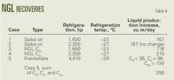
The first case looked at oil spiking at a maximum of 167 cu m/day at –23° C. The next case analyzed C3+ recovery at –23°, –27°, and –29° C.
Table 4 shows the best recoveries are at –29° C. The horsepower (4,610 vs. 2,200), however, doubles for 16% added recovery (256 vs. 215 cu m).
Table 4 shows the scenarios simulated to evaluate NGL yields for a 120-MMscfd recycle gas throughput.
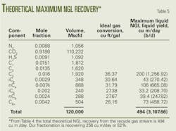
To put NGL recovery in perspective, a calculation was made to determine the theoretical maximum liquid recover based on a flow of 3.3912 million cu m/day (Table 5). The recovery is 256/494 = 52%.
Economics
Table 6 shows the cost for installed refrigeration of 3.3912 million cu m/day. The costs are approximate and were obtained from equipment packagers and project execution experience.
Table 7 shows the revenue recovered from NGL sales.
Economics run from these costs and revenues indicate that the project would pay back in 2.3 years and have a present value of $73 million. Payments were $31.85 million/year and the economics assumed a 5%/year interest and no future value.
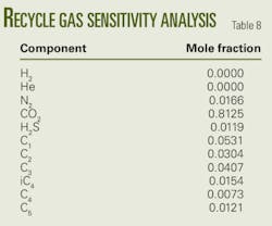
Also the economic analysis included a sensitivity case for a lower mol % recycle gas. The gas analysis in this case was from a mid-phase CO2 injection recycle gas (Table 8) containing 82 mol% CO2. This gas is much richer than the initial 92% CO2 case.
Table 9 shows the simulations for predicting liquid recoveries with the same plant configuration as for the previous case. The table shows the much higher recoveries that lead to a 1-year payback.
Observations
From this evaluation several points were noted as follows:
• Depending on the refrigeration requirements, the process should include dense-phase pumping if possible. Pumping has a lower cost than compression if the process has enough cooling in summer conditions.
• An added advantage of the refrigeration is ethylene glycol dehydration for avoiding hydrates when chilling the gas to drop out liquids. The recycle gas, therefore, is dehydrated without the need of exotic piping for corrosion protection or a hydrate risk when depressurizing or compressing in a centrifugal compressor.
• The maximum recovery of the methane and ethane is insufficient to justify methyldiethanolamine treating to recover the 85,000 cu m/day (3 MMscfd) C1 and C2/120 MMscfd of recycle gas.
• A further refinement of the process simulations found that dropping the separator's temperatures permitted recoveries of 176 cu m/day of NGL for –23° C., 215 cu m/day for –27° C., and 256 cu m/day for –29° C. This is not the case for the oil-spiking case. It appears that the oil will not pick up additional NGL at less than –23° C.
• Installation of the NGL-recovery process equipment should be in modularized increments. The towers, heat exchangers, compressors, and chillers do not have efficient turndowns past ±25%.
Hence, the first phase of the project would install 2.832 million cu m/day (100 MMscfd) units followed by expansion of the refrigeration compression, stabilization, and associated gas compression in 2.832 million cu m/day increments.
The author
More Oil & Gas Journal Current Issue Articles
More Oil & Gas Journal Archives Issue Articles
View Oil and Gas Articles on PennEnergy.com
