Understanding required starting NPSH for centrifugal pumps
Norman P. Lieberman
Process Improvement Engineering
Metairie, La.
As addressed in an earlier article of this series, centrifugal pumps are the most common pumps in a process plant, and an operator’s understanding of how these systems work often will impact how much time, resources, and money a refinery spends (OGJ, Oct. 2, 2017, p. 39). More importantly, however, understanding how to minimize and control cavitation in these systems can prevent catastrophes and save human lives.
The problem
Joe Johnston was the operations manager for the former Amoco Oil Co.’s refinery in Casper, Wyo.
“Norm, I can’t get the new flashed-crude charge pump started. It cavitates as soon as I push the motor-start button.”
“Have you tried raising the liquid level in the crude flash drum to maximum?”
“Yes. That did help, but not enough to get the pump started without cavitating. I don’t want to start up and ruin the $40,000 double-mechanical seal.”
“Have you opened the spillback on the 3-in. discharge-to-suction line?”
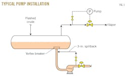
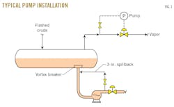
“I tried that. The pump suction got warmer, and it made my problem worse. After all, required net positive suction head (NPSH) increases as flow increases (Fig. 1).”
“Let’s spray cold water on the suction line and pump case, Joe. That will subcool the flashed crude by a few degrees and generate more available NPSH by reduction of the vapor pressure of the flashed crude.”
“Absolutely not! I’m not going to tear off $20,000 of insulation. The maintenance department would shoot me. Look, Norm, I need to get that pump running today. I know that the flashed crude drum isn’t high enough. It’s a design error; it needs to be like 10-20 ft. higher above the pump suction to provide more NPSH for startup.”
“Let’s try opening the discharge valve a fraction of a turn, starting the motor, and then opening the discharge valve really slowly.”
“I’ve tried that. It helps some, but still the pump cavitates. I need a lot more NPSH to get that pump up and running sometime today.”
“Okay, Joe. Let’s go to lunch, and I’ll explain how to get the pump started without cavitation by telling you a story about my daughter who studied engineering for 3 years before graduating with a degree in political science.”
NPSH
“Dad, we learned about pump NPSH today. Professor Albright explained it. It’s really simple.”
“Actually, Irene, it’s not that simple. It’s a complex subject.”
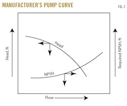
“No, Dad! It’s really very simple. I’ll explain. First, you’ve got your required NPSH. You read that off the manufacturer’s pump curve (Fig. 2). As the flow goes up, the required NPSH always increases. Then you’ve got your available NPSH. I learned how to calculate this yesterday.”
Available NPSH = (P1 + PA) – (VP) × 2.31 ÷ sp gr, where NPSH is measured in feet, P1 = pressure at pump suction in psig, PA = atmospheric pressure in psi, VP = vapor pressure of liquid at pump suction in psi, sp gr = flowing specific gravity.
“All you do is provide enough available NPSH so that it’s equal to the required NPSH at the maximum-design flow rate of the pump. Professor Albright says that you can get enough of that NPSH by either elevating the drum that the pump is serving or subcooling the liquid that is being pumped.”
“Subcooling, Irene?”
“You know, Dad. Maybe like spraying icy cold water on the pump’s suction line. That’ll reduce the liquid below its saturation temperature. Didn’t they teach you this at Cooper Union in New York? We learned this at LSU. It’s really simple.”
Nozzle, piping losses
“There are three factors that increase required NPSH beyond that which you learned at the university and beyond that specified on the manufacturer’s performance curve. One of these factors is nozzle losses and the other is piping friction. For low viscosities, less than 20-30 cst, the nozzle exit loss is DH1 = (0.3 × V2) ÷ 12, where DH1 = loss of NPSH due to acceleration through the nozzle measured in feet, and V = nozzle exit velocity in fps.”
“I made a note, Dad. Good point.”
“The 0.3 coefficient assumes, Irene, that there is no vortex breaker on top of the nozzles (Fig. 1).”
“But Dad, I think most nozzles in refinery process vessels have vortex breakers. What coefficient should I use with a vortex breaker?”
“Good question. I wish I knew the answer. As a guess, you might increase the 0.3 coefficient to 0.5,” I suggested. “And then there’s suction-piping losses due to friction. You can calculate the piping losses as follows: DH2 = (4 ÷ ID) × (DL ÷ 62.3) × (V2 ÷ 27.7), where DH2 = piping loss per 100 equivalent ft measured in psi, DL = density of fluid in lb/cu ft, V = line velocity in fps, and ID = pipe diameter in inches. You can convert pressure loss from psi to feet by (DH2 × 2.31) ÷ sp gr. I’ve assumed an ordinary roughness factor inside the pipe in this latter calculation.”
“But Dad, how do I know the piping-equivalent feet before the plant piping is designed?”
“Good question. Only too often, we don’t know. As a guess, I use the actual distances between the pump and vessel, then double it.”
“But you’ve guessed also at the roughness factor inside the pipe. Dad, I think that roughness is used to calculate the friction factor. If you’ve guessed at the friction factor, you’ve guessed at the suction-piping losses. That doesn’t seem professional! Engineers aren’t supposed to guess.”
The Bhopal factor
“You’re right, Irene. Engineering is a serious business. People die when we’re not careful. You’ve heard about the disaster in Bhopal, India, in 1984?”
“No. That was before I was born. Is this going to be one of your long stories?”
“Over 10,000 people were killed. There was someone from Bhopal in a seminar I recently led. He said there were a lot more people killed than the official number of 3,000.”
“Was the cause of those people being killed…was that because of a pump not working…like it cavitated? Like it didn’t have enough NPSH?”
“Well, yes, but only indirectly. First, I’ll have to tell you a bit more about cavitation. It’s not simple.”
Cavitation symptoms
“Irene, what have you been taught are signs of cavitation in a centrifugal pump?”
“Dad, that’s simple. The pump discharge pressure is erratic and low. Pump flow is also erratically low. Mainly, the pump will make a rattling sound, like shaking a bunch of bolts in a can. Also, operating a pump in a cavitating mode will damage it. The impeller or case will be damaged. But, as long as the required NPSH is a little bit less than the available NPSH, cavitation will be totally avoided. I’m expecting you’re going to tell me it’s not that simple and give me a long explanation, Dad, so shoot.”
“Irene, most pumps that I find cavitating don’t have an erratic discharge pressure unless the suction line or draw-off nozzle is partly restricted. Certainly, discharge pressure may be only 50-70% of the performance curve head. But the discharge pressure is stable, and the pump runs quietly. I call this marginal cavitation, in the sense that if I raise the pump suction head by just a few feet (i.e., 1-2 psi), the discharge pressure may increase from 120 psig to 180 psig. In marginal cavitation, a pump appears to be running on an inferior performance curve, but a bit more available NPSH restores it to its proper performance curve.
“The problem is that even when a pump’s calculated available NPSH exceeds the curve required NPSH by a few feet, fluid as it flows through the pump’s impeller may still partly vaporize. The bubbles of vapor can damage the pump’s mechanical seal, soft-carbon face. This, with time, will cause the seal to leak.”
“I see. But how can that be prevented? That sounds serious.”
“Well, Irene, you have to design the pump suction for extra NPSH beyond the minimum specified by that pump performance curve.”
“But how much extra NPSH is needed to make sure the seal isn’t damaged due to cavitation?”
“My pal, Ken Bloch, wrote a book on this subject.1 Want to read it?”
“No! Is that what happened in Bhopal? The pump seal blew out?”
“Not exactly. The pump seal on their pesticide plant leaked repeatedly. So the pump was bypassed, and they used nitrogen pressure to push the toxic reactant into the pesticide reactor. But, in bypassing the pump, they also bypassed their feed tank’s high-temperature alarm. So when they accidentally got water in the feed tank, it reacted with one of the pesticide chemicals and formed a deadly gas. Without the temperature alarm, the plant operators didn’t realize there was a problem. If the pump had been designed with extra available NPSH, this wouldn’t have happened (see safety note).”
“Gee, all those poor people! Kids, too. And moms and people’s pets. Maybe I will read your friend’s book. But is that the only reason for extra available NPSH when designing a new centrifugal pump?”
Starting NPSH requirements
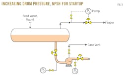
“No, Irene. There’s a more fundamental reason for supplying available NPSH in excess of the manufacturer’s NPSH tabulated on the pump performance curve, like in the diagram I have here (Fig. 3).”
“I’m ready Dad. You talk and I’ll study the diagram. I’ve been looking forward the whole day for this NPSH story.”
“Well, it’s complicated, Irene, so I’ll explain step-wise.”
“Great! Steps. Now I’m really excited.”
“Initially, when an operator starts a centrifugal, motor-driven pump, he or she primes the pump by:
• Fully opening the suction valve.
• Partly opening the vent on the top of the pump case.
• Opening the discharge valve just a little bit, meaning to turn open (that is counterclockwise) the discharge valve about one sixth of a full revolution.
• Pushing the motor start button.
• Opening the discharge valve the rest of the way, as fast as possible, but as limited by not losing the pump suction pressure (Fig. 3).”
“But Dad, wouldn’t it be better to open the valve slowly. Why rush?”
“No, Irene. Running a centrifugal pump at a very low rate causes excessive vibrations, which is bad for the pump’s bearings and seals.”
“But I learned at university that it’s also bad for the pump if it cavitates. So it seems to me that it’s best to watch the discharge pressure. And, if the discharge at P3 becomes erratically low, open up the discharge valve more slowly.”
“You’re right. If the pump cavitates, it will damage the pump’s bearing, but especially the mechanical seal. Most of the pumps used in process plants are self-flushed pumps. That means the seal-flush fluid comes from the discharge of the pump itself. If the pump cavitates, the seal-flush flow stops. Then, the seal loses lubrication and cooling. Better to watch the suction pressure. By the time discharge pressure slips, the pump is already cavitating and seal damage is occurring. By watching the suction pressure, you can avoid cavitation and seal damage before the problem starts.”
“Very interesting. Does that mean, Dad, that there’s always a pressure gauge located on pump suctions?”
“Unfortunately, no, Irene.”
“Then how can the plant operators watch the suction pressure?”
“Here’s how. Process pumps almost always have a spare pump piped in parallel with the main pump. What I do is watch the discharge pressure of the spare pump that is not in operation (with its suction valve open and discharge valve shut). This will be the same as the suction pressure of the pump that is running.”
“Dad, that’s a clever trick. Why is it, then, that we’re not rich if you’re so smart?”
“That’s a long story.”
“Which I don’t want to hear. But I’ve got a better question. Why is it that pumps cavitate so much when they’re being started but not so much when they’re running?”
“Pumps cavitate while being started because of the starting NPSH required.”
“Their what? Is that the same as required NPSH? Or is that something different?”
“Look at the diagram (Fig. 3). When a pump starts, stagnant liquid in the suction line must be accelerated to maybe 3 fps. Here’s the point: centrifugal pumps push, they don’t suck.”
Calculating starting NPSH
Anyone who has commissioned a fixed-speed, motor-driven centrifugal pump will have noted the need to increase the flow slowly. This is not a problem on a variable-speed turbine drive. Then, the turbine speed is increased slowly.
The problem is the need to supply energy to accelerate the fluid in the line feeding the pump. If the suction line is short, this is a problem. If I’m going to switch to the spare pump, for example, 90% of the suction piping is already flowing. I can then start the pump with the discharge valve wide open.
If the suction line is long, however, then I have to provide energy to accelerate the mass of liquid in the suction line. This energy doesn’t come from the pump. It comes from the static head of liquid in the suction line. That is, it comes from the available NPSH. To summarize, centrifugal pumps require three sorts of NPSH:
• The NPSH as shown on the pump curve (Fig. 2).
• Hydraulic losses in suction piping and nozzle exit losses.
• Acceleration of liquid in the suction line.
I’ve called this last item, which is often larger than the first two, the starting NPSH requirement. It’s a function of the length of the suction line and the speed at which the plant operator opens the pump discharge valve.
The accompanying box shows how to calculate the starting NPSH requirement.
Increasing process flow rate
I explained all this to Irene, who brought up a relevant point.
“Dad, this bothers me. Suppose a pump is running close to its design available NPSH. Then, the operator decides to increase the flow by 20%. The required NPSH will increase a lot because the velocity in the suction line will also increase by 20%. Then, the pump will cavitate, the seal flush will stop, and the seal will be damaged due to lack of lubrication. Are pump seals expensive?”
“$40,000 and up.”
“Wow! That’s half the price of the new car you’re going to get me when I graduate. That’s another good reason to design pumps with a lot more available NPSH than the manufacturer’s pump curve shows.”
“You’re dreaming about the car, but yes, Irene. The engineer needs to take these factors into account when deciding on the elevation of vessels. Failing pump mechanical seals are expensive but also dangerous.”
Increasing available starting NPSH in Casper
“Joe, first we’ll increase the drum set-point pressure by 10 psi. Next, we’ll open the discharge valve (Fig. 3) by one fourth of a turn, then start the pump and open the discharge valve in a few minutes all the way.”
“No, Norm. That can’t help. The suction pressure will increase by 10 psi, but the vapor pressure of the flashed crude will increase by the same 10 psi. According to your first equation, the increased vapor pressure of the flashed crude will offset the higher suction pressure.”
“Joe, after 20 min, what you say is true. But at first, due to the 10-min residence time of liquid in the drum, the higher vapor-pressure liquid formed at the vapor-liquid interface will not migrate into the pump suction. If you can get the pump up and running quickly, you will have a temporary surge of available NPSH. It’s a startup trick that I’ve used, Joe. It’s best to instead design the equipment properly and allow for starting as well as running NPSH requirements. Often, while operators are learning this trick, they repeatedly cavitate the pump and damage the seal.”
Minimizing cavitation
“Joe, these are things you can do to help protect mechanical seals from damage due to cavitation:
• Place a pressure gauge with a red mark on the pump suction. Train the operators to open the pump discharge valve as fast as possible, consistent with pressure not falling below this red mark.
• Raise the suction-drum pressure rapidly a few psi, just before starting a pump. Then reduce the pressure very slowly once the pump is operating.
• During normal operations, increase flows very slowly.
• Run near maximum-safe drum level.
• Spray cold water on pump case and suction line to subcool liquid.
• Running two pumps in parallel requires less NPSH – but is often difficult to control.
• Injecting a subcooled, slip-stream into the pump suction will increase available NPSH.
• A discharge spillback to suction line diminishes available NPSH and increases the required NPSH.
• For steam turbine-driven pumps, increase turbine speed slowly.
• Maintain pump-suction screens and keep them clean.
“Also, keep in mind that pump-seal failure is a major cause of fires and explosions in process plants, especially when pumping propane and butane. Make sure the high-pressure alarm on the outer seal-flush reservoir pot is working to alert operators when the inner seal has failed.”
References
1. Bloch, K., “Rethinking Bhopal: A Definitive Guide to Investigating, Preventing, and Learning from Industrial Disasters,” Elsevier Inc., Amsterdam, 2016.
General introduction
Geared to young and seasoned professionals alike, “Beyond back-to-basics: Process principles and concepts” is a new series of articles designed to present a straightforward approach to mastering the principles and concepts all process engineers should be able to apply without the need of a computer.
While simulations and models are useful for examining long-term operational issues, they cannot replace the human logic and reason required when tackling the array of complex—and sometimes life-threatening—situations that occur in process plants.
Using experiences from the author’s more than 50-year career in the process industry, articles in the series will provide approaches to understanding core process concepts in ways that will equip the engineer to walk out of an office, into a plant, and directly resolve process deficiencies via small operational changes or simple retrofits.
This is the eighth article in the series.
Calculating starting NPSH requirement
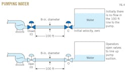
The need to accelerate fluid in the suction of a pump is called the starting NPSH requirement (Fig. 4). To calculate starting NPSH requirement, let’s assume the following:
• Suction line = 100 ft.
• 8-in. suction line.
• Fluid = water at 62 lb/cu ft.
• Initial velocity = zero.
• Final velocity = 10 ft/sec.
Then proceed as follows:
• Mass in line = 2,170 lb
• Change in momentum in line = (10 ft/sec) x 2,170 lbs = 22,170 ft•lb (mass)/sec2
If the operator increases flow uniformly over 100 sec, the change in momentum is:
22,170 ft•lb (mass)/sec2 + 100 sec = 222 ft•lb (mass)/sec2
If 1 lb (mass) = 1 lb (force) x sec2/ft, the force needed to accelerate water in the pump’s suction is 222 lb (force).
Assuming the area of the 8-in. suction line is 50 sq in., starting NPSH required is:
222 lbs (force) ÷ 50 sq. in. = 4.4 psi
or
4.4 psi x 2.31 = 10 ft of water
Safety note
The double-mechanical seal is a safety device. It’s not for reduction of environmental emissions. If the high-pressure or high-level alarms on the reservoir pot are not working, the safety benefits for the double-mechanical seal are largely lost.
An alarm or trip that is not tested routinely will never work in an emergency.
