Innovative method solves catalyst pinning problem
Installation of a restriction orifice in a regeneration gas blower solved catalyst plugging and blowouts in a continuous catalyst regeneration (CCR) tower in Saudi Aramco’s Yanbu refinery. This solution allowed the unit to avoid shutdowns that would have cost the refiner about $600,000/day.
The CCR section of the Yanbu platformer unit was experiencing successive catalyst blowouts, which led to shutdowns of the regeneration section. This caused the platformer section to operate at reduced feed rates, 30,000 b/d vs. 40,000 b/d, and severities, 95 RON vs. 100 RON.
Saudi Aramco’s Yanbu refinery and process department and the control system department worked jointly to troubleshoot and resolve the successive plugging of the CCR tower. They concluded that the problem’s root cause was that the regeneration gas blower had 10% too much capacity.
Available options to reduce pinningthe tendency of catalyst to stick to the screen due to radial thrust exerted by the vapors surrounding itwas to lower the regeneration gas flow. Installation of a restriction orifice on the regeneration-gas blower suction eliminated pinning and normal CCR platformer operations resumed.
Yanbu platformer
The Yanbu platformer unit was revamped in June 2006 from a fixed-bed unit to a CCR unit (OGJ, Dec. 10, 2007, p. 52). Coked spent catalyst from platforming reactors continuously flows to the regeneration tower where coke is burned off and spent catalyst is regenerated in four steps:
- Coke burning.
- Oxychlorination, which disperses catalyst metals and adjusts catalyst chloride.
- Catalyst drying.
- Reduction, which changes catalyst metals to a reduced state. Finally, regenerated catalyst circulates back to the first platforming reactor.
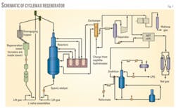
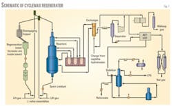
Because the catalyst is in continuous movement, catalyst fines will plug the regenerator screen over time. The CCR must be shut down and the screen removed for cleaning every 12 months. Fig. 1 shows a schematic of the CCR unit.
Incident background
Since the first start-up in June 2006, the regeneration tower has operated with a partially plugged screen due to catalyst fines. These were generated from a containment loss in the platformer reactors due to a weld failure in the center pipe of the first reactor. This failure reduced regeneration gas flow without affecting the CCR operability.
The licensor recommended cleaning the screen as soon as possible. Saudi Aramco shut down the CCR unit for 5 days in January 2007 to clean the regeneration tower screen.
The unit was restarted in black-burn mode. In this operating mode, air for regeneration is introduced in the regenerator tower’s upper half to prevent exposure of highly coked catalyst to high oxygen concentrations, which could damage tower internals.
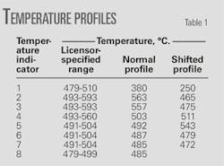
The start-up was normal and the regeneration tower’s temperature profile peaked at the second top temperature indicator (TI) in the burn zone. Regenerator operations for the subsequent 36 hr were normal with regenerated catalyst carbon at 0.095 wt % and spent catalyst carbon at 4.3 wt %.
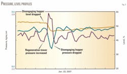
A blowout occurred between the disengaging hopper and regeneration tower, causing the disengaging hopper level to drop to 47% from 52%. The disengaging hopper pressure dropped and the regeneration tower’s pressure increased briefly.
Fig. 2 shows the pressure fluctuation and level drop when the blowout occurred.
The blowout generated many fines and chips that plugged the regenerator screen. A shift in the burn zone’s temperature profile occurred and the peak temperatures shifted to fifth TI, which is at the bottom of the burn zone (Table 1).
Maintaining a proper burn profile in this section is critical for safe unit operations. If the burn profile shifts downward, unregenerated catalyst will enter the chlorination zone, potentially causing catalyst to agglomerate and damage regenerator internals.
In many discussions, refinery engineers and licensor experts on this subject concluded that it is difficult to pinpoint the blowout’s root cause. The team attempted, at the licensor’s suggestion, to stop the regeneration blower and conduct cold circulation of the catalyst to clear the screen. The regeneration tower cooled at 50° C./hr; when the blower switched to low speed at 350° C., a blowout again occurred.
We observed a similar phenomenon when we switched the blower to high speed (3,565 rpm) from low speed (1,785 rpm) during the reheat. But unit performance did not improve.
The refiner, therefore, again shut down the regeneration section due to a repetitive blowout between the disengaging hopper and regeneration tower. We reduced the CCR platformer throughput to 30,000 b/d from the 40,000-b/d design rate and the operating severity to 95 RON from 100 RON to control coke lay down.
Analysis, findings
It is unusual for a blowout to occur in a CCR because it is normally full of catalyst. During normal operations, the catalyst flows down due to gravity.
The disengaging hopper operates at about 9 kg/sq cm gage (128 psig) and the regeneration tower operates at about 2.5 kg/sq cm gauge (35.55 psig). Pipes between the disengaging hopper and regenerator are full of catalyst, which balances the large pressure drop across the two vessels.
If a void is created in the regeneration tower, the huge differential pressure will force the catalyst downward, which will cause a pressure fluctuation and generate fines and dust. The fines will block the regenerator screen, causing the temperature profile to slip.
The problem analysis included these facts:
- One probable cause could be something blocking the catalyst transfer pipe. But this would be a one-time occurrence that would automatically clear after the blowout. Because the blowout recurred, it was obvious that the blowout was not due to plugging of transfer pipes.
- The only difference between the two start-ups was the screen’s condition. Since initial start-up, the unit operated with a plugged screen. The recent start-up was the first one with a clean screen.
- The blowout was clearly related to the blower operation because it had happened on two occasions when the blower speed was switched.
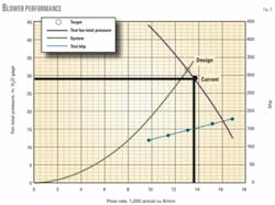
The inspection team conducted a detailed analysis of the blower data. During unit start-up, we conducted a test run to evaluate blower performance. The head delivered was equivalent to 29.53 in. H2O vs. a design head of 30.94 in. H2O. Based on the blower’s performance curve, this motor was delivering 13,300 actual cfm vs. a design of 12,986 actual cfm (Fig. 3).
The team concluded that the blower flow was 2.4% above design, even with a partially plugged screen, indicating that the actual degree of overdesign was even higher.
Once the screen was cleaned, the flow increased, causing catalyst to pin (stick to the screen instead of freely flowing downward) in the regeneration tower. The lock hopper’s removing catalyst created a void at some location in the regeneration tower.
When the differential pressure between the disengaging hopper and regeneration tower was high enough, it forced catalyst to fill the void, creating a blowout. This would also explain the blowout occurring when the blower speed changed.
The first time, when the blower switched from high to low speed, the catalyst unpinned, which caused an immediate blowout. The second time the blower switched from low to high speed, this caused the catalyst to pin.
The blowout did not occur immediately, however. During subsequent heat-up, the catalyst slumped, created a void below the pinned area, and caused a blowout.
The licensor, convinced that the blower was a likely cause for the blowout, agreed to:
- Size a restriction orifice to reduce the regeneration gas flow by 15-20% to avoid pinning. Yanbu refinery engineers kept it ready until the unit was immediately shut down for a screen cleaning. This was installed in the regeneration tower gas outlet line.
- Conduct an inspection of the disengaging hopper and regeneration tower screen.
- Install the restriction orifice in the regeneration-gas outlet line and observe unit performance during restart if the inspection revealed no obvious reason for the blowouts.
Field inspection
Inspectors opened the regeneration tower and disengaging hopper inspection immediately after the blowout. During catalyst unloading, the team found that the last few drums from the disengaging hopper contained fresh catalyst. Aramco had added 12 drums of fresh catalyst to the disengaging hopper during a recent reload.
Because catalyst had circulated for 500 cycles, there should have been no fresh catalyst in the disengaging hopper. This clearly indicated that the catalyst was not moving due to localized catalyst pinning on the regeneration tower screen.
There were no clumps or debris between the disengaging hopper and regeneration tower. The regeneration screen was heavily plugged, and there was no sign of integrity loss or severe damage to the screen.
The team concluded that the root cause for this problem was oversizing of the regeneration-gas blower.
Recommendations
The main available option to reduce pinning was to lower regeneration-gas flow. The least costly option was to install a restriction orifice in the regeneration-gas blower’s suction line to reduce regeneration-gas flow, which would increase the pinning margin.
After discussions with Saudi Aramco engineers, the unit licensor recommended the optimum size for the restriction orifice. It concluded that a 15% reduction in total regeneration-gas flow would improve the pinning margin to 25%.
The licensor designed a restriction orifice with a bore size of 340 mm, which we fabricated and installed in the regeneration-gas outlet line. Higher burn-zone oxygen offset the reduced burn-zone capacity, which fell due to less regeneration gas flow. Oxygen levels increased to 0.95-1.10 mole % from a normal operating value of 0.85-0.95 mole %.
CCR restart
Aramco restarted the regeneration section after installing the restriction orifice. The start-up was smooth without any pressure fluctuations or signs of blowout.
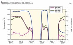
There were no major deficiencies in regeneration blower operations. Temperature profiles across the regeneration tower were normal (Fig. 4).
To test the capacity of the regeneration tower, we conducted a coke-burn test. We slowly increased the circulation to 95% of design and slowly reduced oxygen concentration to 0.8 mole % from 1.0 mole %.
Laboratory results showed that there was less than 0.07 wt % carbon on the catalyst, which indicated complete regeneration. The test results indicated that there was no major reduction in unit capacity.
The authors
Rabea M. Al-Saggaf ([email protected]) is a process engineer in Saudi Aramco’s Yanbu refinery operation engineering unit. He has 10 years’ experience in refining and was involved in initial start-up of the Yanbu CCR platformer. Saggaf holds a BS in chemical engineering from King Abdulaziz University of Jeddah.
Sajeesh Padmanabhan is an engineer in the operations engineering unit at Saudi Aramco’s Yanbu refinery. He has 12 years’ experience in refining and petrochemicals and was involved with the commissioning and start-up of the Yanbu CCR platformer. Padmanabhan holds a BS in chemical engineering from the University of Calicut, Kerala, India.
Hamzah Z. Abuduraihem is a process engineer in Saudi Aramco’s process and control systems department. He joined Saudi Aramco in 1992 and has 15 years’ experience in refinery operations and project management. Hamzah holds an MS in chemical engineering and petroleum refining from the Colorado School of Mines.
Neelay Bhattacharya is a process engineer in Saudi Aramco’s process and control systems department. He has 17 years’ experience in refining and petrochemicals. He joined Saudi Aramco in 2006. Bhattacharya holds a BEng (1990) in petroleum and petrochemicals from Pune University, India.
