Upgrades extend vacuum distillation ejector systems’ service by decades
Jim Lines
Graham Corp.
Batavia, NY
Refinery vacuum distillation units (VDUs) use ejector systems to establish and maintain distillation-column pressure for capturing valuable crude fractions and reducing vacuum residuum. Reliable vacuum separation of crude fractions within residuum of an atmospheric tower, then, requires dependable ejector-system performance.
Ejector systems are intended to support a refinery’s vacuum distillation process over several decades. But ensuring long-term performance reliability of these systems entails sustained investment in rigorous routine maintenance, repair, and operations (MRO) programs.
While robust MRO is increasingly important as refiners strive to increase intervals between planned maintenance shutdowns to 6 years or longer from previously standard 4 or 5-year cycles, leveraging existing assets is also critical as operators contemplate strategic capital expenditures (capex) to increase yields, throughputs, or overall reliability of VDUs. Since ejector systems can be reconfigured with a combination of new and existing equipment to achieve targeted yield or throughput goals as well as extended operating reliability between shutdowns, deciding where and how to invest in these systems becomes paramount for refiners seeking to boost profitability.
To assist refiners in weighing strategic and MRO investments, Graham Corp. recently completed an analysis of VDU ejector systems the company designed and manufactured for installation at refineries between the 1970s and early 1990s that continue operating today. The study specifically focused on gaining insight into how operators have invested over the past 30-50 years to maintain and revamp these original ejector systems to ensure their ongoing, reliable, and profitable performance.
In addition to discussing general recommendations for investments in VDU ejector systems based on results of the study, this article presents three detailed case studies highlighting strategic capital and continuous MRO investments individual refiners have made in their original systems—installed in either the 1970s or 1980s—to drive improved refinery profitability.
MRO, strategic capex overview
While no two refiners were alike regarding their approach to investing in MRO and strategic—or growth-related—programs, analyses based on results of the study indicated similarities among refiners for best practices related to maintaining reliable and healthy VDU ejector-system performance, as well as common themes associated with strategic capex that impacted the original ejector systems.
Throughout a VDU ejector system’s lifetime of what the study confirmed can be 50 years or more, refiners dedicated steady investments to MRO programs aimed at ensuring the existing system maintained regularly safe and uninterrupted operations, especially between planned maintenance shutdowns. Results showed operators devoted strategic capex to ejector-system growth projects intended to enhance VDU operational profitability, including works to increase unit throughputs, improve yields, lengthen periods between scheduled turnarounds, or improve seasonal underperformance issues.
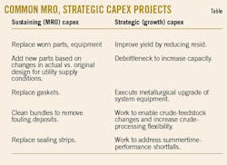
The accompanying table presents common MRO and growth-related investments identified among the refiners.
MRO capex considerations
While ejector systems have no moving parts, an ejector can experience wear from erosion or corrosion. Erosion typically arises from moisture in motive steam that is accelerated to supersonic velocity within the ejector. Wet-steam conditions can often cause erosion on the ejector’s motive-steam nozzle or the inlet diffuser section (Fig. 1). Wet steam occurs when moisture droplets are present in steam supplied to the ejector, which can result from one or more of the following:
- A lack of either insulation or cyclonic steam separators.
- Low velocity in the supply piping to the ejector.
- Lengthy piping distances from steam header to the ejector.
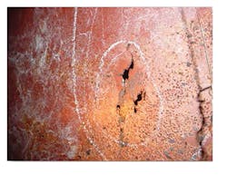
Often stemming from the choice of material for the motive-steam nozzle assembly or the ejector itself, corrosion can lead to a loss of pressure-boundary integrity that results in air leakage and declining system performance (Fig. 2).
Recommended best practice is to periodically inspect the ejector’s motive-steam nozzles and diffusers for erosion or corrosion damage, and this type of inspection should be considered mandatory during every turnaround. Additionally, refineries also should maintain warehouse spares for motive nozzles. If erosion or corrosion damage occurs, replacing these worn components is highly recommended, especially if not doing so would risk an unplanned shutdown.
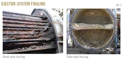
Ejector-system condensers also are at risk of corrosion, fouling, or mechanical damage that can negatively impact the system’s performance. Trend data such as drops in tube-side cooling water pressure, a rise in cooling-water temperature, and changes in shell-side operating pressure, shell-side vapor outlet temperature, or shell-side condensate temperature can be useful indicators to identify if fouling is starting to affect condenser performance. Periodic cleaning of the condenser’s tube and shell sides is recommended when fouling is anticipated.
Fig. 3 shows examples of shell-side and tube-side fouling.
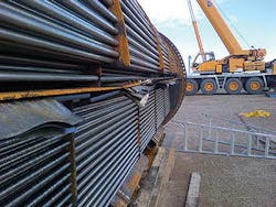
Damage to shell-side sealing strip can arise from corrosion or improper tube-bundle insertion after bundles are removed for cleaning. Damaged sealing strips will render a condenser inefficient due to bypassing of process vapors, resulting in an ejector-system performance break identifiable by a sharply elevated vacuum-column operating pressure (Fig. 4). Sealing strips should be replaced as a best practice each time a tube bundle is pulled for cleaning, with special care to be exercised for bundle insertion to prevent damaging the sealing strips.
When evaluating necessary MRO investments to ensure long-term reliability and performance of a VDU ejector system, operators also should be wary of options that offer seemingly attractive up-front cost savings, as these cost-cutting measures frequently can create long-term issues with the system that result in economic losses exceeding initial short-term savings (see sidebar).
Strategic capex considerations
Strategic capital investments in VDU ejector systems focus on how to leverage existing operating assets to improve operational profitability. This will typically entail assessing how to:
- Capture more vacuum-gas oils by reducing vacuum-tower bottoms (yield improvement).
- Push more barrels through the current distillation unit (greater capacity).
- Extend equipment operating life or enable longer spans between planned shutdowns (metallurgical upgrade).
- Address a summertime performance shortfall.
The three case studies presented in this article examine strategic capex decisions by refiners for VDU ejector system originally installed in the 1970s or 1980s while simultaneously demonstrating how the operators continually invest in these systems to drive improved refinery profitability.
The analysis of the ejector systems performed as part of the broader study and referenced in the case studies identified the following similarities:
- It is not uncommon that the utility supply conditions that formed the basis for the ejector system’s original design do not match current conditions at the refinery. This is often attributable to additional demands placed on the utility plant from new process units, capacity creep, and aging utility-plant equipment, collectively resulting in lower, actual steam pressure to ejectors than the original-design basis envisioned. Lower steam pressure can be detrimental to ejector-system performance, which, in turn, negatively impacts overall VDU performance.
- Maximum cooling-water inlet temperature to the ejector system exceeds the original-design basis. This can result from climate change, increased wet-bulb temperature, or simply additional heat-rejection demands placed on the exiting cooling-tower system. Warmer inlet-cooling water temperatures can have dire consequences on ejector-system performance, ultimately affecting VDU performance.
- Refiners seek to increase feedstock flexibility to gain the economic advantage of processing lower-cost crude oils. Feedstock composition or characterization, however, is likely very different today from that anticipated as the design basis for ejector systems in the 1970s-1990s. Non-condensable gas or hydrocarbon vapors in the overhead load vary across decades, which can have a direct impact on ejector-system performance. Moreover, there can be liquid entrainment or heavier material trapped in the overhead, both of which negatively impact ejector-system performance. It was not surprising to learn through the study that the slop-oil analysis performed today is quite different in mass flow rate or composition from what formed the system’s design basis a few decades back.
While these variances in ejector-system design are often addressed during the scope of broader strategic-capex projects, the ejector system typically undergoes a revamp as part of the indirectly related project to attend to system-performance requirements that differ from original design basis.
The following sections summarize notable cases from Graham’s study and subsequent analysis that, while focused on major strategic capex projects, include examples of continuous investment in the refiners’ respective MRO programs.
Case 1
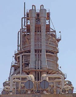
A refinery producing transportation fuels installed a large VDU ejector system at its worldscale-capacity plant. The three-stage ejector system included the first-stage ejector close-coupled to the vacuum distillation column (Fig. 5). The system consisted of two twin-element ejectors, each designed for 50% of total load. The distillation-column overhead pressure was 18 mm Hg, with an overhead loading of 20,000 pounds/hr (pph)consisting of 14 mol % non-condensable gases, 4 mol % hydrocarbon vapors, and 82 mol % steam. Utility supply conditions to the ejector system were 150 psig steam and a maximum cooling-water inlet temperature of 92° F. The ejectors were constructed of all-carbon steel with a 304 stainless steel (SS) motive-steam nozzle. The fixed tube-sheet style condensers—a standard choice for this particular refiner—were all-carbon steel with admiralty tubing and naval-rolled brass tube sheets, all of which was typical for a 1980s ejector system.
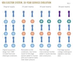
Still operating today, the vacuum-distillation column and ejector system have undergone three strategic capex projects alongside routine MRO investments during their nearly 40 years of operation, with the refinery expanded as well during the four-decade period (Fig. 6).
Major project. About 20 years into operation, the ejector system underwent a large revamp to address utility supply conditions and reduce vacuum-tower resid to improve yields. During the project, the operator identified that, due to additional steam demand within the refinery, actual steam supply to the ejectors was 135 psig rather than the original-design basis of 150 psig. Moreover, the maximum cooling-water inlet temperature to ejector-system condensers reached as warm as 103° F. in the hottest summer months due to added cooling-tower requirements from expanded processing units at the refinery. Climate change also was causing an increased wet-bulb temperature. Because of the lower steam pressure and warmer cooling temperatures, the ejector system had inadequate energy to compress to an elevated condenser-operating pressure.
To improve yields, the distillation tower’s top pressure was lowered to 13 from 18 mm Hg, with overhead loading reduced to 16,000 pph (9 mol % non-condensable gases, 4 mol % hydrocarbon vapor, and 87 mol % steam).
Due to the elevated cooling-water temperature, new and larger first and second intercondensers were required, but it was possible to retain the original aftercondenser and all the ejectors. The project, however, did require new motive-steam nozzles for the first-stage ejectors, as maximum-discharge pressure for those ejectors had to increase to 102 mm Hg, up from 85 mm Hg, due to the warmer water. Condenser materials of construction included brass tubing, and the large first intercondensers were now removable-bundle type due to the extensive shell-side fouling identified.
About 30 years into operation—or 10 years following the yield improvement revamp—the refinery undertook another large strategic capex project to upgrade the system’s first-intercondenser metallurgy to extend equipment operating life and the interval between planned shutdowns. First-intercondenser bundles were upgraded to duplex SS tubing and tube sheets with remaining SS.
At the 38-year mark, the operator executed a metallurgical upgrade of the system’s the first-stage ejectors, during which the original carbon ejectors were replaced with 316 SS ejectors.
MRO investments across the system’s lifetime have included periodical replacement of sacrificial anodes in condenser channels and replacement of various steam-nozzle ejectors.
Case 2
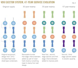
The vacuum distillation column remains in operation today, and the ejector system has undergone three strategic capex projects along with routine MRO investments during its nearly 50 years of operation (Fig. 8).
Major project. Approximately 30 years into operation, the refinery undertook a large revamp of the VDU ejector system to enable production of cleaner transportation fuels. The vacuum-distillation column was converted to a damp-tower design. Tower-top pressure was lowered to 15 mm Hg, with overhead loading at 13,000 pph (7 mol % non-condensable gases, 1 mole% hydrocarbon vapor, and 92 mol % steam).
To reflect current conditions, the system’s maximum-cooling inlet temperature was considered 90° F. rather than the original 85° F. Motive-steam supply conditions remained the same. New ejector-system components included first-stage ejectors, first intercondensers, and second-stage ejectors. The remainder of the ejector system was existing equipment, with the ejector system at this point a three-stage system with parallel 50%-capacity trains. The first intercondenser was converted to a removable-bundle style from its original fixed-tube sheet design.
Materials of construction for the new ejectors and first intercondensers were kept the same as called for by the system’s original design.
At the 35-year point, the previous revamp required additional work after the operator determined that maximum cooling-water inlet temperature was 92° F., causing the hydrocarbon vapors to form a waxy fouling within the first intercondenser that materially lowered the overall heat-transfer coefficient. If the warmer inlet-cooling temperature and fouling that was impacting heat exchange within the system were not addressed, the amount of vacuum-tower bottoms produced would result in a large economic loss for the refiner.
While addressing the system’s warmer-water issues and fouling tendency, the refiner sought to further improve yields by targeting a lower pressure for the vacuum-distillation column. Overhead pressure was lowered to 12 mm Hg from 15 mm Hg, with overhead loading set at 27,500 pph. This deep-cut revamp required new first-stage ejectors and first intercondensers. The remainder of the ejector system was left unchanged other than moving the first intercondensers provided during the previous revamp to the second-intercondenser position within the system. The refiner also elected to use more corrosion-resistant metallurgy, and the new first intercondenser was built with duplex SS bundle rather than the originally intended brass tubes and tube sheets. Studies were completed to determine an overall reliable heat-transfer rate within the first intercondenser, which led to establishing a maximum overall heat-transfer rate for design of the new first intercondensers.
At the 47-year mark, the second and third-stage ejectors were replaced with new sizes because of the amount of cracked gas (non-condensable gas) production and to accommodate doubling capacity of the original supply to provide for improved system performance.
MRO investments included periodic replacement of gaskets, secondary ejectors, bundle sealing strips, and condenser bundles.
Although different from its early-1970s original design, this system continues to reliably operate.
Case 3
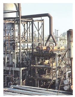
About 45 years ago, a refiner built a grassroots CDU-VDU that began operating in the mid-1970s. The vacuum distillation process was based on a dry-tower design at 14 mm Hg overhead pressure with 2,300 pph of overhead load at 80 mol % non-condensable gases and 20 mol % steam. With previous experience operating ejector systems, the refiner selected condensers of the removable-bundle type as the design basis for condensers of the new VDU ejector system. Utility supply conditions to the system were 125 psig steam dry and saturated and a maximum cooling-water inlet temperature of 90° F. The ejectors were all constructed of 304 SS, while condensers were all-carbon steel with admiralty brass tubing and Muntz-metal tube sheets (Fig. 9).
After operating for some 30 years, the operator noticed actual steam supply to the ejectors had dropped to 118 psig at 480° F. from its original-design basis of 125 psig dry and saturated. The issue was resolved by installing new motive-steam nozzles reflecting true utility conditions as part of an MRO investment.
While the original vacuum distillation column remains in operation today, its ejector system—in addition to routine MRO upkeep—has undergone one strategic capital investment during its more than four decades of service.
Major project. For some time, the refiner was unable to reach the targeted 14 mm Hg tower-top pressure of the original tower’s design, resulting in poor yields. A company performance improvement engineer conducted an overall health check of the ejector system, which included gathering pressure and temperature survey information and an analysis of slop-oil composition and flow rate.
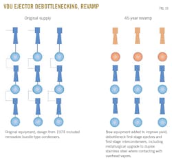
The health check revealed utility supply conditions drastically changed from the system’s mid-1970s original design. With overhead loading eventually becoming difficult under initial-design parameters, the operator determined it needed to redesign the first-stage ejectors and first intercondensers to reflect the new and very different overhead-loading requirements. The revamp targeted holding vacuum-distillation overhead pressure at 14 mm Hg with an overhead loading of 27,000 pph composed of 12 mol % non-condensable gases, 58 mol % hydrocarbon vapors, and 30 mol % steam. The design was based on actual utility conditions of steam at 118 psig at 450° F. rather than the original 125 psig dry and saturated. The maximum cooling-water inlet temperature for the revamp remained unchanged from the system’s original design of 90° F.
As part of this strategic revamp, a metallurgical upgrade was undertaken to install new duplex SS first-stage ejectors and first intercondensers where in contact with distillation-column overhead vapors (Fig. 10).
Routine MRO investments across the system’s lifetime have included periodic replacement of motive-steam nozzles and ejectors, as well as adding new steam nozzles to accommodate a steam-supply pressure of 188 psig.
The author
Jim Lines ([email protected]) recently retired from Graham Corp., where over his 37-year career, he worked as an engineer and in various general management positions. Lines, who continues to provide advisory services to Graham, has authored numerous articles related to heat transfer, vacuum condensers, and ejector systems. He holds a BS in aerospace engineering from the State University of New York at Butler.
