Aramco outlines best practices processfor sour-gas feed MEG system
Saud H Al-Mudaibegh
Megat A. Rithauddeen
Muntazer Alawi
Saudi Aramco
Dhahran
Saudi Aramco has recently resolved major difficulties caused by a closed-loop monoethylene glycol (MEG) regeneration and reclamation system at one of its onshore sour-gas feed processing plants in Saudi Arabia’s Eastern Province that, since its commissioning, has prevented the system from achieving its design capacity and targeted product specifications.
To address the technical issues, Aramco engineers conducted extensive investigations to create a holistic view of the chemistry involved in plant operations. These efforts, alongside independent assessment of the MEG system and its equipment, enabled the engineering team to determine operating issues stemmed primarily from poor design of the MEG system’s original pretreatment and reclamation sections. Results of its investigation allowed Aramco to identify novel methodologies to enhance the MEG system’s design performance and operational reliability, as well as ensure its safe startup.
In addition to discussing the plant’s operating problems and providing the solutions implemented to overcome them, this article presents Aramco’s comprehensive best-practice approach for proper design of MEG regeneration and reclamation systems in sour-gas feed applications based on lessons learned while troubleshooting.
Operations overview
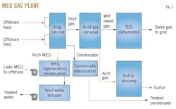
As part of its hydrate prevention strategy for the MEG injection system at a Northern Arabia offshore sour gas field, Aramco installed a closed-loop MEG regeneration and reclamation system at an associated Eastern Province onshore gas plant to manage MEG inventory and regenerate the thermodynamic inhibitor for reinjection at the offshore project’s intermediate injection platform. Commissioned in 2016, the gas plant was designed to process 2-2.5 bcfd of gas from the offshore development (Fig. 1).
Though continuous MEG injection was determined to be the most reliable and cost-effective method of hydrate inhibition for long-distance tiebacks with complex offshore gathering architecture, the plant’s closed-loop MEG system presented unique problems from startup.
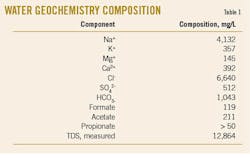
The plant’s feed gas has a high concentration of hydrogen sulfide (H2S; 4 mole %) and carbon dioxide (CO2; 7 mole %) for anticipated dissolved H2S and CO2 contents of about 0.6 mole % and 0.3 mole %, respectively, in the rich MEG feeding the regeneration system. Sampling of water geochemistry executed during the plant’s conceptual design indicated feed would arrive with water containing total dissolved solids (TDS) of about 12,900 mg/l., primarily consisting of Na+ and Cl- (Table 1).1 Therefore, it was important to design the pretreatment and reclamation sections to manage these contaminants.
- Pretreatment removes light hydrocarbons (HC), acid gases, and divalent cation salts.
- Regeneration removes water from rich MEG to achieve a lean MEG concentration of 80 wt %.
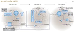
- Reclamation removes salts from lean MEG and keeps the salt content in lean MEG less than 2 wt % (Fig. 2).
Operating issues
Since its commissioning in 2016, the MEG system experienced major problems which prevented it from achieving its designed operating capacity. These included an inability to:
- Meet the lean MEG H2S specification of > 10 ppmv.
- Constantly maintain the required lean MEG concentration of 80 wt %.
- Run the reclamation amid difficulties in operation of the centrifuge.
Additional issues involved a frequently leaking lean-rich MEG exchanger as well as frequent plugging of rich MEG filters, which required numerous filter changeouts.
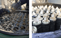
Visual inspection of filters showed fouling consisting of a mud-like material suspended in the fluid, likely originating from drilling-mud residue in the trunkline (Fig. 3).
The following sections describe the investigation’s detailed findings and present the team’s recommendations for enhancing performance of each system for sour-gas feed service.
Pretreatment
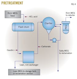
The pretreatment section is designed to remove light HCs, acid gases, and divalent cations such as Ca2+ and Mg2+ by means of injecting hydrochloric acid (HCl), caustic, and potassium carbonate (K2CO3). Section equipment includes a pretreatment flash drum, rich-lean MEG exchanger, clarifier, and rich MEG filters (Fig. 4).
To meet a lean MEG H2S specification of 10 ppmv, HCl is added in the pretreatment flash drum to liberate H2S from the rich MEG stream by removing dissolved weak acid gas (H2S) out of the rich MEG solution. This effectively regenerates the acid gases back into a gaseous form removable from solution through pressure reduction at lower temperature. The pretreatment flash drum also removes CO2 produced by the decomposition of carbonate salts, light HCs, and entrained acid gas.
Solids are concentrated in the clarifier and then directed to the reclamation section for further treatment. The rich MEG feed then passes through particulate filters to remove fine particles before regeneration. Rich MEG is heated in the lean-rich MEG exchanger before entering the MEG flash drum.
Ineffective design of acid injection unit. Ideally, in this pretreatment section, rich MEG is sweetened by liberating H2S gas through acidification of the solution using HCl. Acidifying the sour, rich MEG with HCl is analogous to acidifying drilling fluid with HCl, which results in H2S liberation when pH decreases below 7.2 This is a possible approach when treating produced water having a high sulfate concentration to avoid precipitation of soluble sulfate salts and may also be used to control excess caustic by avoiding the need for a second type of acid on site.3
Nevertheless, considering the small flow rate of injected acid (vs. the large flow rate of rich MEG), it is difficult to correctly mix the two liquids, preventing chemical reactions from occurring as anticipated.
Even after conducting several process optimizations—including reducing operating pressure of the MEG pretreatment flash drum as much as possible—the original system lineup would not enable lean MEG to comply with the targeted 10 ppm (wt) H2S specification. Based on several simulations at various dissolved H2S content in the rich MEG, the lowest achievable H2S concentration was 1,307 ppmv.
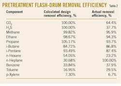
Ineffective design of pretreatment flash drum. Based on design, 100% of all heavy HCs, including dissolved HCs and acid gases from the pretreatment flash drum, would be removed. Actual observation, however, indicated that the pretreatment flash drum did not entirely remove acid gases or the HCs (Table 2). While actual removal efficiency for heavy HCs (C5+) was within range of the design stage, light-end HC removal was not. The presence of non-condensable HCs in the MEG regenerator would lead to high quantities in the regenerator overhead, resulting in higher backpressure than originally intended.
While original design also intended that dissolved C5+ and benzene, toluene, ethyl benzene, and xylenes (BTEX) components were routed with rich MEG to the MEG regeneration section, the design did not account for dissolved C5+ and BTEX in the simulation thermodynamic package. These components were instead desorbed in the MEG regenerator reboilers, flowed up in the MEG regenerator towers, condensed by the MEG regenerator condensers, and then routed to the MEG regenerator reflux drums. A portion of these C5+ and BTEX components returned to the MEG regenerator towers with the reflux water.
Since BTEX is more volatile than MEG, there would be no major consequence on the MEG loop from a process point of view if the MEG system was designed for appropriate carryover of condensate. The following, however, remained a concern:
- An internal reflux of BTEX can be generated in the regenerator tower, causing an overloading of packing in this column.
- C5+ and BTEX could return by batch (not continuously) to the MEG regenerator tower with a high quantity arriving occasionally to—and potentially overloading—the reboiler.
- While BTEX in the rich MEG would mainly flash off in the distillation and lean MEG reclamation units to condense with water, this water—which is used to cool various pumps—may require treating to meet environmental regulations.
Inadequate clarifier design to remove divalent salts. Based on a performance test that involved adding carbonates to a rich MEG sample to precipitate divalent salts, the team observed that salt crystals formed but—instead of settling—remained floating at the MEG solution’s surface. While the clarifier was designed to remove particles with a diameter above 40 μm, actual divalent salt crystals are much smaller (1-20 μm). Based on the anticipated size of salt crystals, the original design did not account for removal of divalent salts.
Poor feed quality. The poor quality of feed gas was mainly due to the excessive influx of solids to the inlet separation plant. Since the MEG system’s startup in early 2016, the rich MEG filters were frequently plugged due to the large volume of solids arriving from upstream operations, which worsened over time as new wells were introduced. This excessive influx of solids eventually led to severe fouling of MEG regenerator reboilers, which in turn caused MEG regeneration performance to deteriorate, resulting in an off-spec lean MEG concentration.
Regeneration
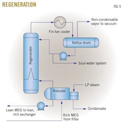
Designed to achieve the lean MEG concentration of 80 wt % and H2S specification of > 10 ppm (wt), the original MEG regeneration section included a regenerator column, reboiler, and lean MEG transfer pumps (Fig. 5). Major problems in the section involved high corrosion and heavy fouling of the MEG regeneration reboilers caused by carryover of drilling muds as well as the presence of salts, C5+, H2S, and BTEX, which consequently led to the section’s inability to meet lean MEG purity and cavitation of lean MEG pumps. The engineering team observed frequent process upsets of the section as plant operations struggled to maintain steady operation of the MEG system. The ongoing upsets led to an important conclusion: If the pretreatment system was working well, the regeneration system should have maintained a more stable operation.
Additional observations revealed that when TDS in the MEG stream was relatively low, no corrosion occurred on the carbon steel or the duplex stainless-steel (SS) material. Operating data indicated that duplex SS is only suitable up to around 6,500 ppm chlorides, which the original system design exceeded.
Reclamation
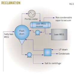
Based on the slipstream reclaiming process (37% of the total lean MEG stream), the MEG reclamation system was designed to keep the lean MEG’s salt content less than 2 wt %. Major equipment consisted of a slurry cooler, circulation heater, reclamation flash drum, centrifuge, vacuum pumps, vacuum separator, booster compressor, booster-gas compressor separator, and brine transfer pumps (Fig. 6).
Vacuum pumps in the section also frequently failed to start. Investigation revealed the issue related directly to the original design’s failure to consider startup conditions, particularly the fact that the upstream system is not under vacuum. This inhibited startup of the section’s vacuum pumps, during which time both the mass-flow rate and discharge pressure were much higher than normal operations, requiring more power than was available.
Considering these operational difficulties, the team assessed the MEG reclamation section’s bypass mode for implementation based on the potential rate of salts buildup, broader industry experiences, and overall operational feasibility.
Salts buildup rate. There are different rules for high and low-solubility salts allowed in a lean MEG system. Based on the gas plant’s sour-gas feed composition, high-solubility salt was originally anticipated to consist mostly of NaCl, with low-solubility salts of calcium carbonate (CaCO3) and calcium sulfate (CaSO4). Based on industry best practices, the amount of high-solubility salt that the lean MEG system can recycle is limited to 2 wt %.4-5 The situation would be more unpredictable for low-solubility salts based on the original system’s design, as it set no clear limit and anticipated divalent cations—depending on their respective temperatures and MEG concentration-saturation ratios—would form scale at the hot section of the regeneration system.
In this case, formation of CaCO3 scales may not have been a concern, as—based on species—the produced water’s bicarbonate concentration was low (e.g., less than stoichiometric to the calcium concentration). The sulfate-to-calcium ratio, however, was almost exactly stoichiometric, and a quick estimate indicated that Ca would most likely precipitate as CaSO4 instead.
Based on the relatively small amount of salts considered by the design and the anticipated low-TDS content indicated by forecasts and results of laboratory analysis, the engineering team demonstrated that the reclamation section could be temporarily bypassed within 80 days of the MEG regeneration system’s start of operation, at which point forecasts showed high-solubility salts content reaching a maximum limit of 2 wt %.For low-solubility salts, scale formation was not anticipated based on the amount of Ca ions in the water chemistry. Estimates indicated that the Ca concentration would reach 165 ppm (wt) after 108 days, notably below the 400-500 ppm (wt) level typically considered to be a threshold for concern.
Considering the regeneration section’s operating conditions, however, the team anticipated moderate scaling could still occur. To address concerns of divalent cations causing scaling at the MEG regenerator, the team devised an option of running the potassium carbonate injection in the MEG system’s pretreatment section.
Industry experience. Broader industry experiences confirm that buildup of carbonate and bicarbonate in an MEG reclamation section is a common problem.6-13 The insoluble carbonate from divalent salts such as iron, calcium, and magnesium will be formed from CO2 and water in the pipeline at the right pH, temperature, and concentration.
Another common problem is formation and buildup of iron solids in the reboiler. The predominant scale of iron carbonate (FeCO3) forms at hot surfaces in the MEG regeneration system. Iron sulfide (FeS) and iron oxide may also deposit in some circumstances. Different strategies can control iron generation and subsequent solids deposition and fouling due to FeS. These include corrosion-inhibitor (CI) injection, pH modification, use of internal coatings, and selection of corrosion-resistant alloys (CRAs).
In one industry experience, severe scaling and damage was observed within 3-6 months at an MEG regeneration system operating without an MEG reclamation section, three of four MEG regenerators suffering extensive internal damage.6 One of the root causes identified was CaCO3 dissolved in rich MEG that precipitated as thick calcite deposits onto the packing surface in the system’s lower section, feed distributor, packing-support plate, and still columns. Different analyses carried out on the deposits and fluids within the lower section concluded that the structures of the primarily CaCO3 deposits were affected by the presence of magnesium and sulfate, with the origin of the deposits determined to be CaCO3 in the drilling mud. Analyses also indicated concentrations of TDS and calcium ions of up to 200,000 mg/l. and about 2,900 ppm (wt), respectively.
Another operator of an offshore gas-condensate field equipped with MEG loops reported a similar occurrence where FeCO3—the main corrosion product—precipitated in the reclamation section’s still columns, with a secondary corrosion product of FeS likely responsible for a carry-under of more than 10 vol % of stabilized condensate emulsion in rich MEG.9 In this case, the operator addressed the buildup of iron solids in the design using CRAs, coatings, and CI injection to protect the flowlines and trunkline. The plant only incurred scaling at the reboiler and not the packing, as the rich MEG routed to the reboiler first, making it unlikely for packing to accumulate any salts absent high-liquid holdup in the reboiler. The emulsion issue and HC carry-under, however, could still pose a risk of condensate carry-under. It was therefore important that Aramco’s plant ensure sufficient residence time in the inlet separator and pretreatment vessel to avoid condensate carry-under into the MEG regeneration system.
Operational feasibility. The team determined that original design of the MEG system’s equipment did not consider bypass operation of the reclamation section. To operate in this mode, the following key equipment would be affected:
- MEG sump. Typically, bottom product from the pretreatment clarifier would be automatically routed to the reclamation section given slurry density downstream of the clarifier circulation pump exceeded a certain value. As this operation was unfeasible, the pretreatment clarifier bottom was intermittently dumped to the MEG sump manually by monitoring slurry density. To minimize the load to the MEG sump—and considering the low amount of Ca ions—carbonate was not injected into the pretreatment system. Based on the assessment, the team determined that 10% of the slurry pump flow to the sump for 1 hr./week should be sufficient to prevent solids buildup in the clarifier. Given the low frequency of these dumping events, it could be practical to drain or flush the slurry line to the sump after each slurry dump sequence. A disposal procedure was also developed to handle slurry accumulated in the sump.
- MEG regenerator reflux drum. Reflux-drum overhead product was routed to the reclamation section’s vacuum pump. As the reclamation section was blinded, a nitrogen blanket on the condensate blowcase for the reclamation product receiver needed to be active to ensure positive flow through the vacuum pump. Since circulating water-lean MEG from the MEG-reclamation product receiver to the vacuum pumps occurs in a closed loop, it can accumulate heat over time and elevate temperatures enough to eventually trip the vacuum separator’s shutdown. This was avoided by introducing a constant supply of clean, lean MEG, or produced water, into the vessel to carry away heat.
- New operating mode. The team executed a new hazard and operability (HAZOP) study to assess the revised operating mode, the results of which did not identify any major areas of concern. No major deviations or any credible consequences were revealed other than the low risks captured by the system’s original HAZOP study, all of which could be easily eliminated, minimized, or managed.
Collectively, the team’s investigations, assessments, and subsequent findings concluded it was feasible to temporarily operate the MEG regeneration system without the reclamation section provided all precautionary measures were implemented and necessary MEG-inventory bleeding was performed to manage buildup of salts in the closed-loop system.
Major findings
The completed study revealed the following major insights into problems affecting the gas plant’s MEG system:
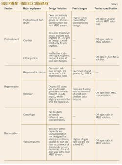
- The originally flawed design of the clarifier and hydrochloric acid injection units allowed salts and H2S to accumulate in the MEG regeneration section.
- The inability to operate the reclamation section greatly contributed to buildup of salts in the system.
- The vacuum pump was not designed for the higher off-gas rate and startup condition under an actual-operations scenario, which in turn impacted operation of the MEG reclamation section and centrifuge.
- The batch-mode operation due to frequent plugging of rich MEG filters, together with sour, rich MEG (including HC feeding the MEG regeneration system), aggravated the ongoing process upsets, the combined effect of which resulted in the reboiler experiencing frequent fouling and transfer pump damage due to cavitation, in turn preventing the regeneration system from achieving the desired lean MEG specification.
- The MEG system’s original pretreatment section was overwhelmed by the excessive amount of solids influx from upstream operations, the presence of which had direct and indirect impacts on the performance reliability of the pretreatment section, downstream filters, and regeneration section.
Table 3 presents a summary of findings for major equipment of the MEG regeneration section.
Based on lessons learned from its experience at the gas plant, Aramco developed the following set of recommendations for approaching future design of an MEG regeneration and reclamation system intended to treat MEG from a sour gas field.
General
General recommendations include:
- Validate and finalize water-in-gas ratio and salt composition before beginning design of the MEG recovery and reclamation system.
- System design should consider solids removal at early startup of the plant, with sufficient well-cleanup to be conducted before commissioning feed gas wells. In addition, an efficient filter-separator should be provided upstream of the MEG regeneration system to avoid contamination from any presence of drilling mud, particularly during startup and commissioning.
- Any chemicals added to the trunkline should be compatible with each other and the MEG solution. Their behavior in an MEG regeneration and reclamation system should also be determined and well-known.
- Content of monovalent salts such as chlorides of sodium and potassium, which affect lean MEG viscosity, should be measured.
- Content of potential scale-forming ions such as divalent cations (Ca2+, Ba2+, etc.) and SO4 should be considered.
- Alkalinity that reacts with CO2 to form bicarbonate and carbonate when equilibrated with produced gas must be minimized.
- A maximum and minimum pH value of lean MEG should be determined based on the goal of avoiding scaling in the system and keeping a low-corrosion rate in the pipelines and MEG injection line.
Pretreatment section
Recommendations regarding the pretreatment section include:
- Consider a full-reclamation section instead of a slip-stream reclamation section by evaporating the total rich MEG feed with the necessary operational flexibility to manage upsets.
- Relocate rich, lean MEG upstream of the pretreatment flash drum to improve HC separation.
- Install permanent higher-capacity rich MEG coalescing filters or a hydrocyclone in the pretreatment section.
- Replace an acid-caustic injection system with a fuel-gas cold stripper. Off gas from the new cold stripper column can either be routed to a sulfur recovery unit (SRU) or flare gas recovery unit (FGRU).
- Install a divalent-salts removal filtration package to enhance an existing clarifier’s performance.
- Replace rich-lean exchanger with a late-frame to spiral-type.
- Provide a complete MEG bypass line to allow for operational flexibility without MEG injection during summer.
- Install rich MEG tanks as part of the pretreatment section.
Regeneration, reclamation sections
Regeneration and reclamation section recommendations include:
- Upgrade reboiler tubes and regenerator internals in the regeneration section by:
- Installing reboilers with corrosion-resistant material based on a worst-case scenario.
- Upgrading regenerator packing and a gas chimney tray to a more robust design to help manage any off-spec H2S carry-over.
- Replace slurry cooler and circulation-type heater with spiral-type.
- Consider using a vertical basket centrifuge instead of a horizontal decanter.
- Provide a control system that allows for automatic and robust operation.
Acknowledgments
The authors would like to thank various people within Saudi Aramco and licensors involved in the successful commissioning and operations of the MEG regeneration and reclamation system. In addition, the authors appreciate the support provided by Saudi Aramco’s project management team, consulting services department, production and facilities development department, and gas operations team. The authors also extend their appreciation to Saudi Aramco management for providing resources required to complete and publish this study.
References
- Nengkoda, A., Nengkoda A., Birkle, P., Harbi, B., Mufleh, J., Awwami, M., Duailej Y., Khaldi, M., Cai, X., Haas, M., and Alharith, I., “Successful Inorganic Scaling Prediction in Early Conceptual Design Phase: Gas Field Development Experience,” SPE Saudi Arabia Section Technical Symposium and Exhibition, Al-Khobar, Apr. 21-24, 2014.
- A. Saasen; A., Omland, T.H., Ekrene, S., Brévière, J., Villard, E., Kaageson-Loe, N., Tehrani, A., Cameron, J., Freeman, M., Growcock, F., Patrick, A., Stock, T., Jørgensen, T., Reinholt, F., Amundsen, H.E.F., Steele, A., and Meeten, G., “Automatic Measurement of Drilling Fluid and Drill Cuttings Properties,” IADC/SPE Drilling Conference, Orlando, Fla., Mar. 4-6, 2008.
- Crawford, S., Korpiel, J., and Velastegui, O., “Degasification by Absorption-Based Gas Stripping,” SPE Annual Technical Conference and Exhibition, San Antonio, Oct. 9-11, 2017.
- Baraka-Lokmane, S., Hurtevent, C., Seiersten, M., Flaten, E., Farrell, M., Bradshaw, O., Hare, S., Bonis, M., Jacob, F., and Carles, N.,“Technical challenges and solutions in a closed loop MEG regeneration system for gas field offshore, UK,” WIT Transactions on Engineering Sciences, Vol. 79, pp. 511-522, 2013.
- Baraka-Lokmane, S., Hurtevent, C., Ohanessian, J.L., Rousseau, G., Seiersten, M., and Deshmukh, S., “Prediction of Mineral Scaling in a MEG Loop System of a Gas Production Offshore,” SPE International Oilfield Scale Conference, Aberdeen, May 30-31, 2012.
- MEG Regeneration Technical Meeting, Society of Petroleum Engineers, Port Campbell, Australia, June 18, 2009.
- Gibson Applied Technology and Engineering Inc., “MEG Regeneration System: Iron Scale,” GATE Keeper Brochure No. GAT2004-GKP-2012.11, November 2012.
- Montazaud, T., “Precipitation of carbonates in the pretreatment process for regeneration of ethylene glycol,” Master’s thesis, Norwegian University of Science and Technology, Trondheim, June 2011.
- Nergaard, M., and Grimholt, C., “An introduction to scaling causes, problems and solutions,” Institutt for Petroleumsteknologi og Anvendt Geofysikk, Norges Teknisk-Naturvitenskapelige Universitet, Trondheim, November 2010.
- Flatten, E.M., Watterud, G., Andreassen, J.P., and Seiersten, M., “Precipitation of Iron and Calcium Carbonate in Pipelines at Varying MEG Contents,” SPE International Oilfield Scale Conference, Aberdeen, May 28-29, 2008.
- Sandengen, K., “Prediction of Mineral Scale Formation in Wet Gas Condensate Pipelines and in MEG Regeneration Plants,” PhD thesis, Norwegian University of Science and Technology, Trondheim, September 2006.
- Babu, D.R., Hosseinzadeh, M., Ehsaninejad, A., Babaei, R., Kashkooli, M.R., and Akbary, H., Carbonates precipitation in MEG loops—A comparative study of South Pars and Bass Strait gas fields,” Journal of Natural Gas Science and Engineering, Vol. 27, No. 2, November 2015, pp. 955-966.
- Brustad, S., Løken, K.P., and Waalmann, J.G., “Hydrate Prevention using MEG instead of MeOH: Impact of experience from major Norwegian developments on technology selection for injection and recovery of MEG,” Offshore Technology Conference, Houston, May 2-5, 2005.
The authors
Saud Mudaibegh ([email protected]) is a process engineering consultant with Saudi Aramco’s upstream process engineering division. He has more than 25 years’ experience in oil and gas processing focusing on gas sweetening, dehydration, NGL recovery, modular process unit design, and fabrication. Mudaibegh joined Saudi Arabian Oil Co. in 1995 and holds a BSc in chemical engineering from King Fahd University of Petroleum and Minerals, Dhahran. He is currently chairman of Saudi Aramco’s oil and gas process engineering committee.
Megat A. Rithauddeen ([email protected]) is a process engineering specialist for Saudi Aramco currently part of the upstream process engineering division. Before joining Saudi Aramco in 2011, he was a process specialist in the process optimization engineering unit in RasGas Ltd., Qatar, and has more than 20 years’ experience in the oil and gas industry in the Middle East and Malaysia. An active member of Saudi Aramco Standards committees for oil & gas processing and flow assurance, Rithauddeen holds a chemical engineering (with honors) degree from Monash University, Melbourne, Australia, He is a chartered engineer and member of the Institution of Chemical Engineers, as well as a certified professional engineer from Malaysia’s Board of Engineers.
Muntazer N. Alalawi ([email protected]) is a lead process engineer for Saudi Aramco’s Wasit gas plant team, which he joined during the plant’s construction phase and for which he served as commissioning leader on a sulfur recovery unit and a gas treating unit. After joining Saudi Aramco in 2010, he previously worked as a process engineer in sulfur recovery, handling, pelletizing, and exporting. Alalawi holds a BSc (2010) in chemical engineering from King Fahd University of Petroleum and Minerals, Dhahran.
