Infrared scans improve Permian acid-gas removal operations
Eric Teletzke
Brett Roberts
INEOS Americas LLC
Houston
In 2020-21, INEOS Americas LLC was contracted to complete a series of projects to diagnose and provide solutions for issues occurring in formulated acid-gas removal systems at several natural gas processing plants throughout the Permian basin.
This article presents an overview of INEOS’s approach to and experience with troubleshooting operational issues within those units, demonstrating how a combination of simulations, temperature and solvent monitoring, and use of infrared (IR) scans enabled the gas plants to improve acid gas removal systems operations.
Temperature, solvent impacts
Because of their high energy efficiency, potential to enable increased treating capacity, and ability to meet treated liquid specifications, formulated amines often offer the best solvent choice for carbon dioxide (CO2) removal systems. There is one limitation to these solvents, however, that is frequently overlooked: high reaction rates with CO2 combined with the relatively low amine-to-gas ratio required when using formulated solvents can result in excessive temperatures inside the amine contactor during operation.
These excessive temperatures—which cause diminished CO2-removal and higher corrosion rates of carbon steel absorber shells—can even occur in plants operating below the 0.45 mol/mol rich-loading industry standard for methyl-diethanolamine (MDEA)-based formulated solvents.
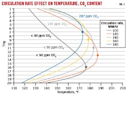
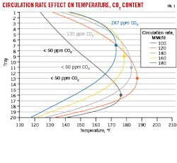
In one troubleshooting simulation for a Permian gas plant operating at normal conditions, INEOS found circulation rates can have a major effect on the temperature profile and CO2 content of treated gas (Fig. 1).
As gas rates increase at a constant amine circulation rate, average temperatures in the column increase, and the maximum observed temperature (bulge) moves higher. At gas rates of 160 MMcfd and 180 MMcfd, the maximum temperature occurs on trays 9 and 7, respectively. In these two cases, where the maximum temperature occurs in the top half of the amine absorber, large amounts of CO2 are slipped. This can have serious implications in cryogenic units and LNG applications with strict CO2 limits.
In all the analyzed scenarios ranging from 100-180 MMcfd, the solvent loading was less than 0.45 mol/mol, reinforcing the fact that many additional factors must be considered when evaluating new and existing amine units. Proper solvent selection, acid gas partial pressure, temperature, contamination, and many other parameters will have considerable effects on performance.
Infrared scans, liquid flow paths
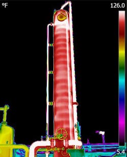
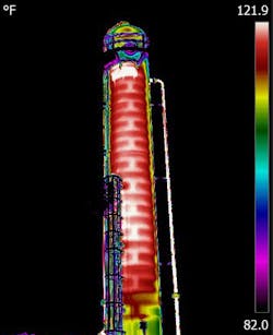
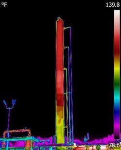
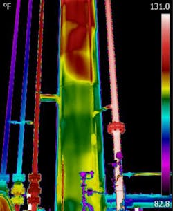
INEOS uses IR scans to observe tower reaction profiles as a tool for visualizing liquid flow paths through the amine contactor. In 2021, scans collected from two Permian gas plants revealed good visibility of the liquid flow as it traveled down each tray of the column and through the downcomers.
Fig. 2 shows the liquid profile on single-pass trays in Tower 1. Fig. 3 shows the liquid profile on double-pass trays in Tower 2.
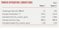
In both plants, the amount of CO2 removal in the amine contactor was low, resulting in minimal temperature increase across the tower (Table 1). Infrared scans, however, were still able to reveal liquid flow paths via the slight temperature differences between the liquid and gas phases in the tower.
Elevated CO2 concentrations
Commissioned in 2016, a Permian basin acid-gas removal plant using a formulated amine solvent began experiencing higher-than-expected CO2 levels in its residue gas and contracted INEOS to troubleshoot the issue. At the time, the gas plant was treating 19 MMcfd of gas, a major turndown from its 120-MMcfd design rate.
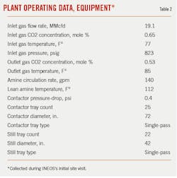
During an initial site visit to diagnose the problem, a team of INEOS engineers using gas chromatographic (GC) analyzers measured concentrations of the plant’s inlet and residue (outlet) gases at 0.650 mole % CO2, and 0.533 mole % CO2, respectively (Table 2). A properly functioning amine unit on the solvent used should remove CO2 to less than 100 ppm (0.01% mole % CO2) in the treated gas.
To troubleshoot the problem, INEOS subsequently executed a full walkthrough of plant operations to better understand the site’s unique process flow and equipment, as well as to collect data on amine system operating conditions. The team also conducted IR scans on the amine contactor to diagnose potential hydraulic limitations affecting CO2 removal, as these scans allow engineers to observe temperature differences between liquid and vapor phases on the contactor wall.
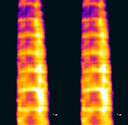
While IR scans of a properly operating amine contactor show a visible liquid flow path through the entire tower, scans INEOS collected at the Permian gas plant revealed evidence of contactor weeping when the tower was operating at low turndown rates, as the liquid followed an irregular path through the tower (Fig. 4). Scans showed heavy liquid flow on the right side of the tower but hazy, irregular flow on the left side. The bottom four trays revealed the strongest evidence of an irregular flow pattern, with scans showing no observable liquid clearly following the path of downcomers on the tower’s left side.
Turndown gas rates appeared to provide inadequate force to hold a liquid level on the trays, and simulations confirmed a vapor flood for the tower calculated at less than 20%.
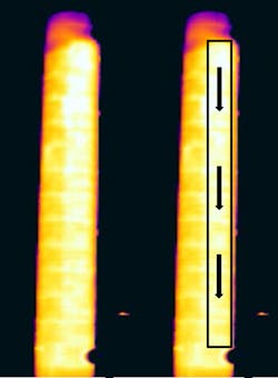
IR scans taken at the site also revealed evidence of channeling in the plant’s tower, where liquid flow appeared much heavier on the tower’s right side (Fig. 5). While the irregularities could have been the result of low gas rates and subsequent low vapor flooding in the tower, it was still possible that mechanical issues in the tower also were contributing to the issues.
Observations
In addition to uncovering the irregular hydraulic flow pattern in the amine contactor, INEOS engineers observed the following details during their walk-through of the plant:
- There were two gas lines that combined with the treated gas stream: an absorber bypass and an interconnect from another acid-gas removal system.
- The interconnect pipe was warm to the touch and appeared to be flowing. If this line was flowing into the treated gas stream, it could have contributed to alterations in the CO2 concentration.
- The gas-gas exchanger was bypassed during the entire site visit, ruling out possibility that an exchanger was contaminating the treated gas with untreated gas.
- Although the lean amine set point was 120° F., according to the IR camera, the amine appeared to be losing about 10° F. before hitting the contactor. This type of temperature drop could potentially result in foaming if the lean amine temperature dropped low enough to cause condensation of hydrocarbon in the gas during treatment.
- The plant received an additional 10 MMcfd of gas during the visit but was unable to maintain this rate due to upstream limitations.
- About every 10 hr, the residue GC experienced an episode during which CO2 concentration spiked to over 1% before slowly declining to 0.5%. At the time of the visit, INEOS was unable to confirm if this reading was a GC or process issue because spikes occurred at the same time additional gas was entering the plant.
- Based on results of a 3-day operating analysis, spikes in the inlet GC to or above 1% did not correlate to corresponding alterations in the inlet GC. That is, when the residue GC experienced a spike to 1% or higher, the inlet GC remained at 0.65%. This would not be physically possible unless there was either a measurement error or another source of CO2 combining with the treated gas stream downstream of the amine contactor.
Results
Based on its fact findings and simulations, INEOS predicted that—even with low vapor flooding occurring in the tower—the plant’s amine contactor should have been removing more CO2 than it was. The team was able to confirm for the operator that this discrepancy in projected CO2-removal rates amid the episodes of residue gas spiking to 1% CO2 pointed to another CO2 source combining with the treated gas stream.
Following the troubleshooting study, the gas plant operator confirmed to INEOS it subsequently discovered a cracked bypass valve allowing > 80% of the sour gas stream to bypass the amine contactor completely. CO2-spikes of greater than 1.0% corresponded exactly to the molecular sieve regeneration cycle, indicating the mole sieve was absorbing CO2 from untreated gas and releasing it into the process gas upon regeneration every 10 hr.
Equipment damage discovery
As part of a separate study, INEOS employed IR scans to reveal physical damage to unit internals at a Permian gas processing plant in Texas.
After returning the plant to service following a maintenance shutdown, the operator observed an elevated differential pressure of 9.5 psig across the amine contactor. Initially believed to be an instance of foaming, the operator added an antifoam agent to the system to help control foaming incidents with the amine solvent used by the plant. In this case, however, the antifoam was ineffective at reducing the differential pressure and liquid holdup occurring in the tower. As a result of the liquid stacking in the amine contactor, the plant was forced to reduce gas rates to prevent carryover of the amine solvent.
To troubleshoot the issue, INEOS collected amine samples, which showed no signs of contamination or foaming. The flash tank also was skimmed for hydrocarbon but did not show any notable layer of hydrocarbon at the time of sample collection.
Without any evidence to suggest that contamination or foaming was causing the high differential pressure in the amine contactor, INEOS conducted IR scans to search for possible signs of tray damage or potential hydraulic issues.
Once completed, the scans showed an irregular temperature pattern across many of the trays. The issues were most pronounced in the column’s lower trays, where pockets of temperature variations occurred in a diagonal orientation across each deck and the downcomers (Figs. 6-7). In a healthy tower, temperatures should have been mostly uniform horizontally across the tray decks and downcomers, while in this case temperature pockets did not align with the orientation of either trays or downcomers.
Based on INEOS analyses of IR scans and process data presented in the troubleshooting study, the operator determined the best course of action was to shut down the unit to carry out a thorough inspection of the tower. During the inspection, the operator’s team discovered nine trays were either dislodged or damaged. With the shutdown already underway, the team was able the repair-replace the impacted equipment and restore the amine contactor to normal operations.
The authors
Eric Teletzke ([email protected]) is global development manager for INEOS GAS/SPEC Technology Group, where he specializes in the design, operation, and optimization of amine systems for applications including shale gas processing, LNG, refining, tail-gas units, liquid treating, and carbon capture. He holds a BS (2007) in chemical engineering from the University of Texas at Austin.
Brett Roberts ([email protected]) is a regional manager and engineer for INEOS GAS/SPEC Technology Group. He has worked in both the midstream and downstream sectors, specializing in amine unit operations across a broad range of applications in the US and Latin America. Roberts holds a BS (2015) in chemical engineering from Texas A&M University.
