Study investigates premature failure of magnesium anodes
A recent survey of magnesium sacrificial anode cathodic protection systems installed on Bahrain Petroleum Co. (BAPCO) pipelines in 1998 revealed that many of the anodes had failed prematurely and stopped achieving proper protection levels.
This article looks at BAPCO’s Khuff gas distribution system and the investigations carried out into the failed anodes, reasons for the failures, and recommendations for remedial work. It focuses on the use and suitability of sacrificial-anode systems vs. impressed-current systems for the long-term cathodic protection of buried pipelines in desert and reclaimed land areas.
BAPCO pipeline system
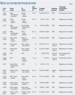
BAPCO supplies natural gas through a network of aboveground transmission pipelines and buried distribution pipelines to customers in Bahrain. The buried pipeline network consists of about 45 miles (70 km) of pipelines of various diameters ranging from 6 in. to 18 in. (150-450 mm).
The coating systems for primary corrosion protection include coal tar epoxy, three-layer polyethylene (PE), and fusion-bonded epoxy (FBE) systems.
Table 1 summarizes the pipeline network.
The Khuff gas system operates at pressures up to 1,000 psig (69 barg). External corrosion protection of the pipelines is achieved primarily via external coating systems.
As a further corrosion-protection measure, the buried pipelines are cathodically protected, either by sacrificial (galvanic) cathodic protection (CP) systems, which are based on magnesium or zinc anodes, or, as in the case of three pipeline sections, by impressed-current cathodic protection (ICCP) systems which use magnetite anodes powered by conventional transformer-rectifier units.
The CP systems are monitored annually, and performance of the installed CP systems is assessed by conventional measurement of pipe-to-soil potentials at designated test locations installed on the pipeline routes.
Pipe-to-soil potential data collected during the routine surveys are compared with relevant international standards to determine conformance with the criteria recommended. Other data, such as open-circuit anode potentials and anode output current, are also measured and recorded during the routine surveys.
During review of the data collected in the 2003 annual survey, a number of magnesium anodes appeared to have failed within only 4-5 years of installation. Of these failed anodes-especially in the case of one recently installed pipeline-some were not connected to the pipeline at the time the CP system was commissioned; and yet the survey data indicated failure of the anodes. The apparent premature failure of these anodes was investigated to develop an appropriate strategy for improving the longevity of the pipelines’ CP systems.
Principles
Cathodic protection has been used for many years to protect metal structures, such as steel ships and pipelines, from electrolytic corrosion by making the structure the cathode in an electrochemical cell, either by applying an electromotive force directly (in the case of impressed-current CP systems), or by putting it into contact with a more electropositive metal (in the case of galvanic CP systems).
For pipelines, a small electric (DC) current is applied to the surface of the pipeline to be protected by an anode groundbed connected to a transformer-rectifier or by galvanic anodes. The structure adopts a more negative (cathodic) potential with respect to its environment.
Also in the case of pipelines, CP is normally used with an external coating system applied to the pipeline, which acts as the primary defense against corrosion and reduces the surface area of the pipeline exposed to the surrounding electrolyte (soil, water), thereby reducing the current required to cathodically protect the pipeline.
Three pipeline sections within BAPCO’s distribution network have impressed-current cathodic protection (ICCP) systems. These use magnetite anode groundbeds and conventional transformer-rectifier units as the external DC power supply for the anode beds. The remaining pipelines are protected via galvanic CP systems that utilize sacrificial anodes of magnesium or zinc.
Galvanic anode systems are based upon the natural potential difference that exists between the steel (cathode) and the sacrificial anode. The anode and cathode must be in a continuous electrolyte (soil-water). As a result of the potential difference, electric current (DC) flows from the anode (which is sacrificed) through the soil-water to the steel.
Specifications for galvanic anode cathodic protection systems often call for a system design life of 20 years. It may indeed be shown by theoretical design calculations that a sufficient mass of anode can be provided to realize any given design life requirement, based upon the electrochemical characteristics of the anode material chosen, current requirements, and likely current output from the anodes.
Experienced CP practitioners, however, have long been aware that, in practice, the performance of land-based galvanic anode installations is much more difficult to predict.
In many cases, land-based galvanic CP systems are known to fail within 5-10 years from commissioning. Some operators allow the use of galvanic anodes on pipelines to provide temporary protection only, pending the installation and commissioning of permanent ICCP systems.
Galvanic systems
As part of the routine maintenance activities carried out on BAPCO’s pipelines, galvanic anodes which become depleted or are consumed are replaced as required. The need for replacement is determined by analysis of the routine survey results, in particular the anode’s open-circuit potentials and current outputs.
As stated earlier, review of the 2003 routine survey data revealed that a number of magnesium anodes that had been replaced as part of routine maintenance had failed within 4-5 years. This occurred on a number of pipelines throughout the distribution network and further investigation began.
Hidd to ISPAT pipeline
The pipeline chosen for the initial investigation into early anode failures, and which is the subject of this article, is the 10-in. (250 mm) diameter L465 pipeline from Hidd Metering Station (HMS) to Hidd Steel Plant (ISPAT).
This pipeline has been constructed, but it has not yet been commissioned; it is not interconnected with any other piping system or aboveground structures and is thus effectively isolated.
During 1997-99, expansion of the distribution network included the installation of the 10-in. pipeline from HMS to ISPAT. The line is installed in an area of reclaimed land and above sea level, although it is close to the shore.
The fill material used for reclamation was dredged from the sea bottom. The pipe material is API 5L Grade B coated, and the pipeline has a factory-applied FBE coating, with heat-shrink sleeves applied at field weld joints. The coating was 100% holiday tested prior to backfilling. The backfilling specification required a sand cushion of 150 mm surrounding the pipe.
CP design
The CP system was designed in accordance with the recommendations (as stated in the design document) of the following referenced standards:
• BS 7361, Part 1: 1991.1
• DNV RP-B401: 1993.2
• NACE RP0169-92.3
• Shell DEP 30.10.73.31-GEN.4
The documented BAPCO design includes the following:
• Design life of 30 years.
• Pipeline surface area of 1,931 sq m.
• Current requirement of 0.30172 amp (equivalent to 0.1562 ma-2 for FBE coated pipe)
• 14 anodes for protection.
• Anode material weight of 96.55 kg (3.4 oz) for design life.
• Five anodes for design life.
• Resistivity along pipeline route of 29.02 ohm-m average.
• Anode utilization factor of 0.75.
The CP system design calculations used were industry standard; e.g., modified Dwight formula for anode resistance, standard current, and standard anode weight requirement calculations. (It should be noted, however, that none of the above referenced internationally accepted standards or standard calculations make any reference to a factor for self-corrosion of the anode material.)
On reviewing the calculations, we found that the number of anodes required for protection is significantly less than 14; so we assumed an additional safety factor was applied.
The final CP system design adopted called for the installation of fourteen 21.8 kg prepackaged, high potential (-1.7 v vs. copper/copper sulfate reference electrode [CSE]) magnesium anodes, located at equal spacing along the pipeline length.
CP system installation
The anodes were installed according to the design and installation specification and in a vertical configuration, with the top of each anode below pipe invert level. Anode lead wires and anode connection-pipe test leads were routed to finished grade level and terminated in surface test facilities in the normal manner.
On commissioning of the CP system, the pipeline achieved satisfactory levels of protection following initial polarization, with only 4 of the 14 installed anodes connected to the pipeline. The remaining 10 anodes were left disconnected.
Review of a postcommissioning close interval potential survey (CIPS) report, which was carried out in October 2000, showed a potential profile along the pipeline route with on potentials on the order of -1.15 v and instant off potentials around -0.95 v. No mention is made of how the instant off potentials were achieved, but it is assumed that simultaneous interruption of the anode connection cables was adopted.
CP system survey data
The survey data in Table 2 show that from 2001 onwards, three of the four connected anodes appear to be acting as a current pickup point from another DC source, such as an adjacent CP system. Thus, the pipe instant-off potentials are more negative than the on potentials, and the measured anode current is negative (reversed). The anode open circuit potential is also insufficiently negative because the anodes are acting as cathodes.
It further means that the initial satisfactory potentials could be entirely due to this third-party current pick up, which would explain why there was only a need to connect 4 out of 14 anodes at the time of commissioning. This cathodic effect extended the anode life. By 2004, however, the anodes had been consumed and were no longer acting as current pickup points.
The survey data also show that as early as 2001 the potentials observed at all test stations had begun to decay from their post-commissioning 2000 levels. The current output from the magnesium anodes was minimal, with only Anode No. 12 passing any measurable current at 6.44 ma. It should also be noted that at Anode Nos. 3, 6, and 9, the anode current values were negative, indicating a flow of current from the pipe to the anode.
The pipe-to-soil potentials at these locations also show the pipeline becoming more negative as the anode is disconnected, whereas the reverse would normally be the case.
By 2003, the pipeline potentials had deteriorated so much they were all in the range -600 to -630 mv with respect to CSE; i.e., effectively natural potentials. It is particularly noteworthy that the open-circuit anode potentials, with one exception (Anode No. 14), had also decayed to almost natural carbon steel values.
The output from the installed magnesium anodes, therefore, had begun to deteriorate within 1-2 years from commissioning date, and the anodes appeared to be completely depleted within 4 years of commissioning. Thus, a decision was made to investigate this in greater detail during the 2004 routine maintenance program.
Site investigations
Following the routine survey in September 2004, three anode locations were selected for excavation to allow visual inspection of the installed anodes. Two anodes were excavated which had never been connected to the pipeline (Anode Nos. 2 and 11), and one anode was excavated which had been connected since commissioning (Anode No. 3).
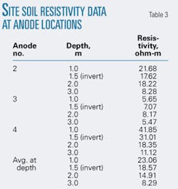
Soil resistivity measurements were carried out at each anode location, with the Wenner four-pin method. Table 3 shows the resistivity test results that were found to be broadly in line with the predesign resistivity data.
Prior to excavation, potential and current measurements were taken from each anode and found to be in line with the results obtained during the routine survey shown in Table 2 (2004 results). Because it was not known whether the anodes had actually been consumed or had perhaps passivated, a temporary external current source (12-v battery) was connected between the anode and pipe leads, with the battery’s positive battery terminal connected to the anode lead and the negative terminal connected to the pipeline lead. The energized pipe potential showed an immediate increase to between -2.65 and -4.07 v with respect to CSE.
The battery was disconnected after 5 min, and the pipe potential was observed to decay rapidly back to its pretest level, with anode output current also reverting to zero.
The test was not conclusive but at least demonstrated that the temporary connection of an external DC power source had no effect in terms of restoring anode operation, and therefore the reduction in anode output was not due to the presence of a coherent film of corrosion products.
The anodes were then excavated by hand, carefully tracing the anode and test leads and exposing the anodes.
The anodes were correctly installed in a vertical orientation below pipe-invert level (Fig. 1). The cotton sack containing the gypsum, bentonite, and sodium sulfate backfill material was partially intact, and the backfill material remained in place around the anodes when they were removed from the excavation (Fig. 2).
The hardened backfill material was then carefully broken away from the anode in order to expose the anode itself, with care not to disturb the anode cable connection and encapsulation.
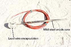
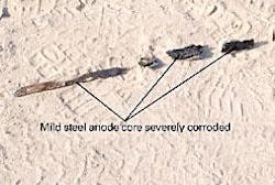
The backfill material broke away easily and cleanly, revealing that the only potion of the anode remaining was the mild steel (MS) core of the anode. The anode lead connection and encapsulation was found to be intact (Fig. 3).
null
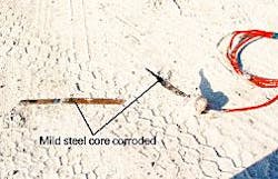
This process was repeated for all three anodes under investigation, with identical results. The only difference was the state of consumption of the MS anode core, which in the case of Anode No. 2 (Fig. 3) was intact and only showing slight rusting. In the case of Anode Nos. 3 and 11, the MS anode cores were more severely corroded. (Figs. 4 and 5).
Survey results
Taken together with the site investigations outlined above, the survey results suggest that of the 14 high-potential magnesium anodes which were installed on the HMS to ISPAT pipeline, 13 anodes (93%) were completely consumed. The survey suggests that the anodes may have been in an advanced state of depletion within 1-2 years of installation and had certainly been fully depleted within 4 years of installation.
Remember, there were only 5 anodes required by the design to obtain a 30-year life, but 14 were installed. In theory, a life expectancy of 84 years should have been obtained.
The open-circuit anode potential recorded at Anode No. 14 remained at -1,530 mv vs. CSE, which is anomalous to the remainder of the results and suggests that this anode may not have suffered the same degree of consumption as the other anodes. Even if the anode is 90+% consumed, i.e., if a small amount of magnesium alloy remains, the observed potential would still be that of magnesium.
Thus, the only conclusion that can reliably be drawn from the anode potential at Anode No. 14 is that some anode material remained, i.e., the degree of consumption of the anode was between 0% and 99%.
At the time of writing, it has not been possible to excavate Anode No. 14 to determine its condition, although this would be a useful exercise.
The most striking observation is that, even when the anodes were not connected to the pipelines at any time during the operational period, they were nevertheless consumed within the same timescale as the anodes which had been connected.
As a completely isolated entity placed in the ground, not in contact with any other metallic structure, the nonconnected anodes should have remained inert-this was obviously not the case, leading to the conclusion that consumption of the anodes occurred in large part due to self-corrosion of the magnesium alloy.
The galvanic cathodic protection system had therefore failed after achieving only 5-10% of its intended design life, despite the design being carried out with due diligence and best practice in accordance with internationally accepted recommendations and the inclusion of a significant safety factor.
While the average soil resistivity along the pipeline route may be classified as “corrosive,”1 such resistivities are certainly common throughout the eastern Gulf Cooperative Council region, especially in coastal areas. Further, the system design allowed for this low-resistivity value in determining the mass of anode material required to achieve the required design life.
The investigations outlined in this article are limited to a single pipeline installation, but similar conclusions may be at least tentatively drawn from the deterioration of magnesium anodes observed on other BAPCO pipelines on which they were installed.
The nature of the BAPCO pipeline network, with many pipelines of relatively short length, makes the installation of galvanic anode systems attractive, due to their inherent simplicity and low initial installation cost.
However, this option may be less attractive in terms of life-cycle cost if there is a need to replace anodes every 2-3 years. It is expected that further investigations on other BAPCO pipelines will be carried out to determine if similar effects have occurred.
The outcome of these investigations will then be used to determine a more appropriate strategy for providing cathodic protection to the pipeline network, for example by providing an integrated impressed current cathodic protection scheme. These findings could have important implications for the future design of cathodic-protection systems where galvanic systems are being considered for long-term onshore pipeline protection.
The standards currently available for CP system design provide no reference or factor to be applied to allow for self-corrosion of the anode material.
This investigation indicates that accelerated consumption of magnesium anode material has occurred due to self-corrosion effects. This in turn has resulted in premature failure of a complete galvanic cathodic protection system within 3 years of its installation.
It is reasonable to suggest, therefore, that galvanic CP systems should only be considered for short-term protection of pipelines (about 2 years maximum), at least under the conditions outlined here, until or unless a reliable prediction of anode self-corrosion effects can be incorporated into the design process.
This study only considered the performance of magnesium anodes. Some operators, including BAPCO, use aluminum-indium activated zinc anodes for onshore pipeline CP. It has been observed by the authors, however, that zinc anodes have been prone to passivation effects in some circumstances.
Passivation is a contrasting phenomenon to self-corrosion, through which the anode material suffers from a buildup of adherent corrosion product on its surface such that it effectively stops passing current.
The development and use of “activated” alloys are intended to ensure that passivation does not occur. It is therefore reasonable to assume that this process will enhance self-corrosion and lead to reduced anode life.
Acknowledgments
The authors acknowledge the permission and assistance provided by the Bahrain Petroleum Co. BSC during the site investigations and preparation of this article. The authors also thank Kevin Kendell for his contribution in carrying out the technical review of this material. ✦
References
1. Cathodic Protection, Code of Practice for Land and Marine Applications, BS 7361, Part 1, 1991.
2. Recommended Practice Cathodic Protection Design, DNV RP-B401, 1993.
3. Control of External Corrosion on Underground or Submerged Metallic Piping Systems, NACE RP0169-92.
4. Design of Cathodic Protection Systems for Onshore Buried Pipelines, Shell DEP 30.10.73.31-GEN.
Based on presentation to the Pipeline Rehabilitation & Maintenance Conference, Manama, Bahrain, Jan. 29-Feb. 2, 2005.

