Test protocol guides selection of wet-gas corrosion inhibitor
A proper corrosion-inhibition test protocol helps ensure the success of increasingly expensive offshore oil and gas projects.
Several offshore wet-gas pipelines worldwide carry high concentrations of acid gas across long distances under hydrate-forming conditions. Some of these pipelines use glycol for hydrate control. Under certain conditions, severe corrosion can occur in these pipelines without corrosion inhibitors.
A laboratory protocol that recreated system conditions developed corrosion inhibitors suitable for wet-gas systems with glycol.
Modeling and knowledge of the specific operating facility then allowed assessment of inhibitor effectiveness under system conditions.
With effective corrosion inhibition, lower cost carbon steel can replace more expensive corrosion-resistant alloys.
Subsea multiphase production flowlines often use ethylene glycol and diethylene glycol for hydrate control. Many subsea production systems regenerate the glycol at the separation platform, reusing it by injecting it at the subsea well manifold, sometimes many miles from the glycol regenerator.
The perception pervades that wet-gas pipelines treated with glycol can often operate without corrosion inhibitors, particularly if the system is pH-stabilized.
Wet-gas pipelines with glycol, however, can in some cases experience severe corrosion in the absence of corrosion inhibitors.
CO2 corrosion of carbon steel sometimes decreases when glycol forms part of the aqueous mixture, as compared to systems without glycol. Studies have found the retardation of corrosion to correlate with a factor given by de Waard.1-3
One study found that the anodic reaction decreased strongly with increased glycol concentration.1 But thermostatically-controlled glass cells under natural convection conditions set the basis of that study. Since natural convention generated the velocities in the test, they were gentle and not able to disturb the protective inhibitor film formation.
Several gas condensate pipelines have used pH stabilization with glycol as a hydrate inhibitor.4 A fluid velocity of 3 m/sec and 6 bar CO2 at temperatures of 20° C. and 100° C. provided the basis for flow-loop corrosion studies.4 Corrosion rates in these experiments decreased with time as protective film formed. Glass-cell corrosion experiments with glycol solutions containing H2S-CO2, however, sometimes led to pitting corrosion.5 Pitting occurred in experiments that had a pH of 6.5 at 60° C.
Modeling the line to understand the operating conditions of the offshore system helps develop inhibitors for such systems. Corrosion tests replicated appropriate operating conditions. This article uses the results of modeling a hypothetical mixed-production pipeline in high-shear conditions to understand the performance parameters needed for a corrosion inhibitor to protect an actual offshore pipeline.
The results demonstrate that, in the high-flow rate conditions tested, ethylene glycol is not acting as a corrosion inhibitor.
Previous modeling
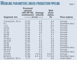
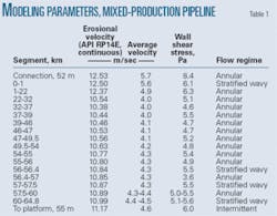
Previous studies conducted modeling with an illustrative mixed-production pipeline (Table 1).6 The calculations coupled the Briggs-Brill correlation with the Taitler-Duckler flow maps and did not account for the presence of glycol. The wall exhibited sheer stresses of 3.6-8.4 Pa.
Table 1 also provides erosional velocities with API RP14E for continuous service. The velocities in the pipe lie well below erosional velocities. The flow pattern varies between stratified wavy, intermittent, and annular. Annular is the most common.
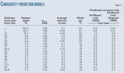
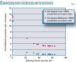
Table 2 lists models used to estimate corrosion rates absent a corrosion inhibitor.2 3 The high partial pressures of carbon dioxide make this system a corrosive system, suitable for treatment with available corrosion inhibitors. Fig. 1 shows the estimated uninhibited corrosion-rate profile as a function of distance. The de Waard, Lotz, Dugstad model3 assigns a greater importance to mass-transfer dependent velocity effects, making its assessment of corrosion rate higher at lower temperatures than the de Waard and Lotz model.2
The pipeline contains considerable partial pressures of carbon dioxide (0.39-2.48 bara). The high temperatures (75°-100° C.) in the system make it highly corrosive. Estimated uninhibited corrosion rates as high as 13.6 mm/year for a pipeline with a 17.5 mm WT place a premium on the use of corrosion inhibitors to protect the line. The pipeline operates predominately in the annular dispersed flow regime but sometimes changes to the wavy stratified regime. Water-to-hydrocarbon ratios in the production lines vary from about 1:1 to 1:5. Shear stresses are moderate in the pipeline systems, all below 25 Pa.
Inhibitor selection
The type of offshore structure, temperature and pressure profiles, flow regime, corrosion-risk assessment, and ability to ensure sufficient concentration of effective corrosion inhibitor components to the pipe wall at all parts of the pipeline without chemical or physical deterioration should guide inhibitor selection.
Laboratory testing to select corrosion inhibitors can be placed in three major categories: corrosion inhibitor’s compatibility with system fluids, corrosion inhibitor’s compatibility with system facilities, and corrosion inhibitor’s performance.
Tests on corrosion-inhibitor fluid compatibility eliminate undesirable inhibitor candidates.
The types of materials used in an offshore system determine the compatibility of the inhibitor with them. Important information obtained from modeling, such as temperature, pressure, composition, and volume ratios of different phases in the system, aids the selection of appropriate inhibitors from tests that use this information explicitly or previous tests performed in similar conditions.
The combined use of previous results and tests specific to the given conditions allow a greater and more complete selection of products and improves the speed of selection in finding economic solutions for corrosion control.
Inhibitor compatibility
Specific tests evaluated the effectiveness of standard corrosion inhibitors (A and B) through the test protocol.
• Solubility of corrosion inhibitors in MEG. Adding 5,000 ppm of each corrosion inhibitor to MEG and solutions of MEG in water ranging from 50% to 80% MEG determined the solubility of corrosion inhibitors in MEG. Both corrosion inhibitors were completely soluble in MEG.
• Stability of corrosion inhibitors at higher temperatures. Both individual chemical components used to formulate the selected corrosion inhibitor and the finished product should exhibit a high degree of stability following many hours of heating at higher temperatures in an MEG-water mixture. Studies used carbon-13 NMR with intermediates in 24-hr tests at 240° F. to determine the intermediates’ stability. Comparative spectra showed that each ingredient in the inhibitors had a high degree of stability in MEG-water mixtures at higher temperatures.
Another test refluxed Inhibitors A and B in MEG for 24 hr and looked for signs of solids. Corrosion tests then used the solutions to ensure that the inhibitors were still active.
Both inhibitors were stable in hot glycol. Both studies suggested that the inhibitor would not form solids and would not degrade readily in hot MEG-water solutions.
• Emulsion tendency. The tendency of the corrosion inhibitor to emulsify produced fluids is an important test criterion. A high emulsion tendency for a product can increase oil carryover to greater than mandated limits or inhibit oil-water separation. Emulsion testing typically is most accurate when performed in the field. Where actual production has not started, however, laboratory tests can indicate which product is more acceptable.
Conducting a “shake bottle” test can measure emulsion tendencies. The test shakes condensate and brine combined at a specific ratio and containing inhibitor for a certain amount of time at a fixed temperature, measuring separation of the hydrocarbon and brine across time. The interfacial pad volume also makes measurements.
Table 3 provides the results of this test for Inhibitors A and B. The fluids containing Inhibitor A completely separated within 10 min. It took less than 2 min for the fluids containing Inhibitor B to separate.
• Foaming in MEG. Bubbling nitrogen through a specified volume of brine containing a specific amount of glycol evaluates the tendency of an inhibitor to foam in MEG. Stopping the gas flow after a specific period prompts the foam to collapse, with the time this takes to occur recorded. Neither inhibitor caused foaming.
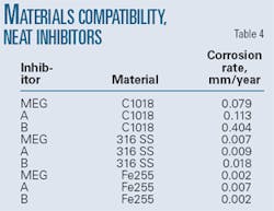
• Materials compatibility. The selected corrosion inhibitor must exhibit low corrosivity against metals that it may contact in storage, handling, and injection. Tests weighed flat rectangular coupons of different materials used in the system and placed them in a glass bottle to which corrosion inhibitor had been added. The bottles were then placed in autoclaves, with the pressure cells sealed and filled three times with nitrogen. Ovens set to 110° C. heated the coupons for 48 hr before they were removed from the bottles, cleaned, and reweighed.
Converting the weight loss to a mm/year corrosion rate indicates the aggressiveness of the corrosion inhibitor against the particular material. These tests used MEG as a control. Table 4 shows corrosivity data for Inhibitor A, Inhibitor B, and MEG. Inhibitors A and B were nonaggressive against Ferallium 255 or 316 stainless. Inhibitor A was less aggressive than Inhibitor B against C1018 (0.113 vs. 0.404 mm/year).
Corrosion inhibitor may contact nylon umbilicals during injection, requiring determination of the compatibility of the chemical with this material. Tests exposed nylon specimens to either 100% corrosion inhibitor or MEG for 48 hr at 110° C. before removing them and inspecting them for changes in weight and hardness.
Table 5 includes results showing inhibitor and MEG compatibility testing with Nylon 11. Inhibitor B dissolved the entire Nylon 11 coupon, rendering it unsuitable with the material. Nylon 11 absorbed Inhibitor A and became brittle with exposure to 110° C.
Performance tests
Additional tests evaluated the inhibitors’ effectiveness.
• Sparged autoclave tests with partitioned brine. Inhibitors must be present in sufficient concentration in the water phase to transport to all pipe surfaces. A specified ratio of condensate and brine first partitioned the inhibitors in the sparged autoclave tests.
The brine used had 50,000 mg/l. chloride. It and the condensate were previously sparged with nitrogen for about 1 hr before use.
The experiment first mixed a specific concentration of inhibitor with brine. The test than added hydrocarbon, shook the mixture, and allowed it to separate and stand for a given interval. The aqueous phase was then slowly and carefully withdrawn and added to a small autoclave which had been degassed. The experiment then heated this phase to 110° C. and added carbon dioxide to 345 kPa.
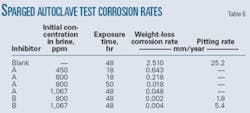
Table 6 provides the measured general and pitting corrosion rates for carbon steel samples in a partitioned brine with different inhibitors. Weight loss measured the general corrosion rates, while pit depths measured with a microscope with a calibrated vernier dial calculated pitting corrosion rates.
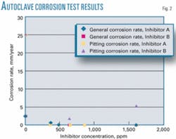
Both the general corrosion rate and pitting corrosion rate indicate high uninhibited corrosion rates at low velocities. The data further indicate that both Inhibitors A and B retard general corrosion if concentrations are sufficient. Pitting corrosion occurred in both the blank and brine solutions containing Inhibitor B but not in solutions containing Inhibitor A.
Fig. 2 shows the general and pitting corrosion rates as a function of concentration.
• Rotoclave tests. The rotoclave used in this test operated at 3,000 rpm, based on a shear stress of 220 Pa. Intermittent flow exerts instantaneous shear stresses much higher than the average shear stress (25 Pa). Testing at elevated shear stress levels ensures the reliability of the corrosion inhibitor under conditions of high-instantaneous shear rates.
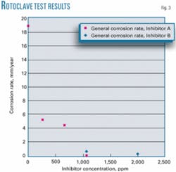
Table 7 gives the measured general corrosion rates in rotoclave tests at 110° C. with a specified brine-to-hydrocarbon ratio for different concentrations of corrosion inhibitors. Inhibitors A and B both substantially reduced corrosion; to 0.2 mm/year and 0.01 mm/year at concentrations of 1,600 ppm and 1,067 ppm, respectively, from an uninhibited rate of 18.9 mm/year.
Fig. 3 plots the measurements as a function of concentration.
Severe conditions
A modified high-speed autoclave test at 90° C. and 2.4 MPa (348 psi) CO2 gauged performance in severe conditions. The HSAT used an open-cage spindle containing flat coupons rotated at different speeds to generate high local shear stresses on the leading edge of the coupons.
HSAT experiments used different amounts of hydrogen sulfide, different chloride levels, and different hydrocarbon and brine ratios. The tests used a rotation speed of 1,200 rpm. Each test lasted 120 hr. The aqueous brine used 40% MEG and 60% sodium chloride brine.
Table 8 shows the results of the test without inhibitor at 90° C., 2.4 MPa (348 psi) CO2, and 1,200 rpm with different percentages of hydrocarbon, concentrations of chloride, and concentrations of hydrogen sulfide. Extremely high rates of corrosion occurred at the different chloride levels and percentages of hydrocarbon, with severe levels seen even without hydrogen sulfide.
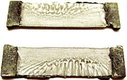
Fig. 4 shows a top view of coupons corroded without inhibitor in a test with a brine of 15,000 mg/l. at 2.4 MPa (348 psi ) CO2, 50 ppm H2S, and 1,200 rpm in the rotating cage. Fig. 5 shows an edge view of the coupons. The corrosive conditions of the tests yielded severe mesa corrosion.
null
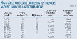
Table 9 shows the results of the test with different concentrations of inhibitor. The table also contains the results without any inhibitor. The use of inhibitor drastically reduces the severe mesa corrosion found in its absence.
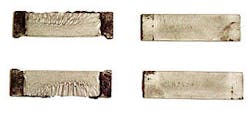
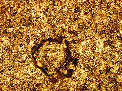
Fig. 6 compares coupons with and without inhibitor. Inhibitor reduced corrosion rates to between 0.09 mm/year and 0.31 mm/year from rates as high as 23.88 mm/year. Microscopic examination of the coupon showed pitting when 1,000 ppm of corrosion inhibitor was used in a test with a brine of 15,000 mg/l. at 2.4 MPa (348 psi) CO2, 50 ppm H2S, and 30 Pa (1,200 rpm) in the rotating cage (Fig. 7). Increasing inhibitor to 1,500 ppm eliminated the pitting, indicating this as the appropriate concentration of inhibition for these conditions.
null
Field use
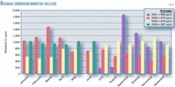
Corrosion Inhibitor A has effectively controlled corrosion in a wet-gas pipeline with regenerated glycol for more than 4 years.
The corrosion inhibitor stays with ethylene glycol in the regenerator and survives high-temperature regeneration with minimal degradation, ensuring that small amounts of corrosion inhibitor are needed to maintain the required concentration. The system in the field injects corrosion inhibitor into the lean glycol that returns to the satellite platforms. The corrosion inhibitor retained heat stability to 116° C.6 and has been used in a system in which regenerator temperatures reached 135° C.
Fig. 8 shows the variation of residuals with time at the satellite coalescers.
Multiphase flow modeling guides the selection of different inhibitors to use with the system across its operating conditions. The information generated from the modeling helps to choose test conditions that simulate field conditions. Modeling results, however, do not guide a complete test protocol. Chemical application experience also plays an important role. Overboard water quality weakens the laboratory protocol, since these measurements optimally should be made in the system after start-up.
Construction of an offshore facility may use many metals and elastomers. The selected chemical must also be compatible with these materials.
Inhibitor A worked well through all parts of the proposed protocol, showing that it is possible for a corrosion inhibitor to pass this series of tests. Equally important, however, other products did not pass the protocol, making them less suitable for application.
Severe mesa corrosion occurred in a 40% MEG-60% brine system, with 5% and 20% hydrocarbon, both with and without hydrogen sulfide.
Acknowledgments
The authors thank Tim Kruger for help with this article.
References
- Guldbransen, E., and Morand, J.H., “Why does glycol inhibit CO2 corrosion,” Paper No. 221, NACE Corrosion 98, San Diego, Mar. 22-27, 1998.
- De Waard, C., and Lotz, U. “Prediction of CO2 corrosion of carbon steel,” NACE Corrosion 93, Paper No. 69, New Orleans, Mar. 7-12, 1993.
- De Waard, C., Lotz, U., and Milliams, D.E., “Predictive model for CO2 corrosion in wet natural gas pipelines,” NACE Corrosion 91, Paper No. 577, Cincinnati, Mar. 11-15, 1991.
- Dugstad, R., and Nyborg, M., “Flow assurance of pH stabilized wet-gas pipelines,” NACE Corrosion 03, Paper No. 314, San Diego, Mar. 16-20, 2003.
- Kvarekval, J., and Dugstad, A., “Pitting corrosion mechanisms on carbon steel in sour glycol-water mixtures,” NACE Corrosion 04, Paper No. 737, New Orleans, Mar. 28-Apr. 1, 2004.
- Ramachandran, S., Ward, M.B., Bartrip, K.A., and Ahn, Y.S., “Corrosion inhibitor development for offshore gas flowlines,” NACE Northern Area Western Conference, Calgary, Mar. 8-11, 1999.
The authors
Sunder Ramachandran ([email protected]) is a senior developmental scientist at Baker Petrolite in Houston. Ramchandran’s expertise includes corrosion and molecular modeling and the development of high-shear corrosion inhibitors. He holds PhDs in chemical engineering from both Colorado State University in Fort Collins and the Indian Institute of Technology.
Sebastian Mancuso is a chemist at Baker Petrolite in Houston. His expertise includes corrosion and corrosion inhibition and boiler-cycle chemistry. He holds a BS in chemistry from the University of Central Florida in Orlando.
Young Soo Ahn is a senior development associate at Baker Petrolite in Houston. His expertise covers corrosion inhibitors, drag-reducing agents, and other specialty chemicals. After obtaining his BS and MS degrees in chemistry from Seoul National University, Ahn undertook post-graduate coursework at the University of Virginia in Charlottesville and the University of Tulsa.
