New design uses ambient pressure insulated LNG pipeline offshore
A new LNG pipeline design improves on existing technology by reducing pipeline costs and maintenance requirements and increasing pipeline reliability.
LNG is currently the fastest growing hydrocarbon fuel in the world. While natural gas as a primary fuel is forecast to grow at 3%/year during the next 2 decades, LNG is forecast to grow at double that rate over the same period.1 Additional facilities for the production and transportation of LNG will be needed in the foreseeable future, and as a result new technologies will emerge to address possible cost, safety, and reliability issues.
For example, loading and unloading LNG require special terminals designed to handle the cryogenic liquid. Terminals at the loading site are normally close to the liquefaction plant, and traditionally, on the offloading end, the terminal is near a storage facility and regasification plant.
Proximity of the onshore terminals to water access has prompted a review of increased shipping traffic in congested waterways.2 As terminal-siting concerns build over pressures from environmental and public safety issues, there is a trend to consider moving terminals offshore.3
Given that both production and import of LNG may move more offshore, a safe, efficient, and reliable transfer system is needed. This article discusses how a new LNG transfer system takes advantage of recent developments in insulation and fiberoptic-sensing technologies to address the issues that confront long-distance, subsea cryogenic pipelines.
The configuration, with patent pending at the end of June 2005, is the culmination of conceptual designs which began in the 1970s with a subsea LPG pipeline for a Middle Eastern LPG terminal and continued into the 1980s with the first subsea LNG pipeline for an arctic LNG ship system in Alaska.
LNG pipeline applications
Terminals are required for both the loading and offloading of LNG. For locations with sufficient deepwater access close to coasts, terminals may consist of jetty structures and breakwaters where tankers can be moored and offloaded via the standard loading arms.
Offshore terminals are an attractive alternative where transfer conditions are less favorable due to shallow waters, congested shipping, mooring situations, and lack of community acceptance or permitting difficulties. Although such terminals exist, they have been widely used for loading of crude oil and oil products for many years; no offshore LNG terminals containing subsea LNG pipelines are in use today.
The most dominant advantages of LNG offshore terminals are the lower costs for construction and operation, and the possibility of locating the terminal in deeper water. That eliminates the need for dredging and increases safety. This also reduces voyage time because LNG carriers need not enter and maneuver in congested waters.4
LNG carrier berths can be located away from confined waterways, thereby increasing safety and security while at the same time preventing costly civil works. Furthermore, impairment of new and existing shipping traffic will be minimized.
A subsea pipeline can transport the LNG from and to an offshore terminal, thereby eliminating the need and cost for a connecting trestle.
With current subsea cryogenic pipeline designs, LNG can be transferred efficiently up to 20 miles.
Current technology
Current pipeline technologies for cryogenic products, such as LNG, use both flexible hoses and rigid pipe. The former is limited to short-distance loading and offloading hoses because of the high expense and the limitation of insulation. Rigid pipelines must be used for longer distance. The LNG pipeline technology discussed in this article addresses these pipelines.
Current designs and methods for rigid cryogenic pipelines typically involve the use of low-pressure or vacuum environments in an insulating space around a product pipeline. While low-pressure or vacuum systems often provide relatively good insulation, the operation and maintenance of such systems tend to be costly and frequently become problematic where such pipelines are submerged on, or even below, the seabed.
Other difficulties are also often encountered, most typically associated with thermal expansion and contraction due to cooling, compression, and structural stability. For example, one current technology accommodates the contraction with INVAR (36% nickel steel), which has very low expansion-contraction properties. In such a configuration, the INVAR product transportation line is contained within an external steel casing pipeline with a partial vacuum on the insulated annulus.
While thermal expansion is almost completely avoided, various disadvantages nevertheless remain. For example, INVAR steel is relatively expensive and often cost prohibitive. Moreover, generation and maintenance of the low pressure (e.g., 100 mbar) in the pipeline assembly requires considerable energy and cost over the life of the pipeline.
In other known designs, contraction and expansion capabilities are improved with the use of bellows. This design incorporates bellows, one in each segment (about 50-ft long) of the pipeline, which is a self-contained, pipe-in-pipe segment, and uses vacuum insulation. However, the use of bellows along the length of the pipeline typically increases production costs and complicates manufacture, handling, and maintenance. The bellows methods are somewhat more costly and both are more expensive than the LNG pipeline technology presented.
The bellows method has significant disadvantages in reliability and durability, both with the bellows and with the maintenance of vacuum. For a subsea application, reliability and durability are even more critical.
Design
Pipelines transporting material at subambient temperatures, and especially cryogenic materials, can be constructed so that the pipeline has both increased mechanical stability and desirable thermal insulation properties while maintaining a mechanically simple structure that is relatively inexpensive to manufacture and install.
The new LNG pipeline design embodies these desired characteristics with a newly available aerogel insulation in a pipe-in-pipe environment that is designed as a structural element.
In the new design, a number of bulkheads (nonmetallic, hybrid, or metallic) and spacers create an annular space between the product pipeline and the outer casing pipe, where the annular space is partially filled with a high-efficiency microporous or nanoporous insulating material. The bulkheads are configured (and coupled to the inner and outer pipeline) such that the bulkheads transfer the contraction-induced axial compression load on the inner cryogenic product pipeline(s) to the outer jacket pipeline.
In most cases, the pressure in the annular space will be ambient pressure. Consequently, the system functions as a structural column, with thermal insulation maintained in the annular space in an ambient-pressure environment, thereby eliminating the need for expensive alloys, vacuum generation and maintenance, or expansion bellows.
More particularly, the bulkheads that connect the inner and outer pipelines at the ends of the pipeline balance compression forces with rigidity of the outer pipeline. In such a configuration, contraction forces are transferred to the external pipeline, which is thereby compressed.
To prevent buckling, spacers (e.g., thermally isolating) are placed around the inner product pipeline to maintain a predetermined distance between the pipes, while further cryogenic insulation material (e.g., nanoporous or microporous material) is placed around the remaining surface of the product pipeline. Additionally, the pipeline design advantageously allows use of 9% nickel steel for the product pipeline to reduce cost of manufacture.
Several grades of stainless steel have been evaluated for the configuration and, depending upon the service requirements and pipeline design, it has been determined that the following materials would be suitable for use in the configuration:
• Type 316 stainless steel (ASTM A312).
• 9 Ni Steel (ASTM 333 Grade 8 pipe).
Further mechanical stability may come from placing the pipe-in-pipe assembly in a restraining environment. For example, pipelines may be placed in a trench with select back-fill material installed over the pipeline. Therefore, the load on the bulkheads and outer pipeline is transferred into the surrounding soil. Similarly, the pipelines can also be constrained aboveground. For example, the pipeline may be placed on a foundation of sleepers that contain sliding or gimbaled supports.
It is generally preferred that two bulkheads cooperate to seal the annular space between the bulkheads with the annular space kept at ambient pressure. However, there may be an advantage to keeping the annular space at a slightly higher pressure than ambient when incorporating a leak-detection system into the overall design. In this case, any change in annular pressure results in a detection of a leak, either external or internal.
A 9% nickel steel is preferred for an LNG product pipeline with carbon steel for the outer pipeline. The preferred thermal insulation is a high-performance nanoporous aerogel product in blanket or bead form installed within the annular space. Such aerogels may be applied in any form; however, flexible sheets or spray-coated materials are preferred.
While the above cryogenic pipeline design and methods are preferably used for LNG offloading and offshore LNG terminals, numerous alternative uses are also suitable.
For example, other uses could include transfer lines for floating LNG production, storage, and offloading vessels, liquid hydrogen and oxygen fueling lines for aerospace or other applications, and all applications that need to transport cryogenic products through pipelines.
Additionally, other uses include LPG transport or transport of gases and liquids having a temperature below ambient temperature (e.g., liquefied carbon dioxide, LPG, and liquid nitrogen.
Configurations
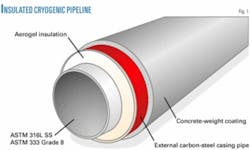
The present LNG pipeline technology uses a highly efficient, thermal nanoporous insulation in the annular space between the inner and outer pipes, and this material is kept in an ambient-pressure environment as a result of the space being sealed by bulkheads (Fig. 1).
The current practices for cryogenic pipelines involve the use of low-pressure or vacuum environments to achieve the thermal performance characteristics of the insulation systems.
The new LNG pipeline technology uses the highly efficient insulation in an ambient environment. The nanoporous insulation is hydrophobic because the pour spaces are smaller than the molecules of water; therefore, the insulation does not absorb water. The insulation does not degrade in the presence of water or moisture, an important consideration for thermal efficiency and for operational maintenance.
A novelty of the new LNG pipeline technology is the application of nonmetal bulkheads and spacers, metallic bulkheads, or hybrid bulkheads and spacers to cryogenic product pipelines such as those transporting LNG. The resulting pipeline bundle design is a structural element, which addresses the thermal contraction and expansion loads without resorting to expansion bellows or ultra-low thermal contraction alloys.
The method eliminates the need for both the expensive alloys and the vacuum pipe-in-pipe. The bulkheads transfer the contraction-induced axial compression load on the inner cryogenic carrier pipe(s) to the external jacket pipe. The pipe(s)-in-pipe system functions as a structural column, with thermal insulation maintained in the annular space in an ambient-pressure environment.
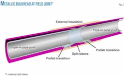
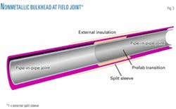
Metallic bulkheads at the ends effect sealing of the annular space and allow transfer of the contraction-inducted axial compression load (Fig. 2). Additionally, nonmetallic bulkheads provide additional sealing or water stops and additional load transfer throughout the pipeline configuration (Fig. 3). Between these bulkheads, and to facilitate fabrication, nonmetallic spacers or centralizers provide additional support and structural rigidity.
As an example, an LNG carrier pipe that would be rated for cryogenic service and the transfer of thermal loads through the bulkheads would be a 9% nickel steel, while the jacket pipe is carbon steel, and the thermal insulation is a high-performance, nanoporous aerogel product in blanket or bead form installed within the annular space without vacuum and under ambient pressure.
Benefits
The new LNG pipeline design improves the current technology in three areas:
• Reduction of pipeline cost.
• Increased pipeline reliability.
• Reduction in maintenance.
The design has a system to monitor the pressures and temperatures within the cryogenic carrier pipe. In the annular space, the system monitors the efficiency of the thermal insulation and detects internal leaks or external internal interference from a security point of view. A fiber optic, real-time monitoring system has been developed by others to provide a means during operation and maintenance to monitor the subsea cryogenic pipeline.5
Typical installation
Installation of prefabricated and assembled pipelines can be done by numerous known methods, especially the towed method. The pipeline may also be installed by a surface barge. The final method of installation depends upon the final configuration of the pipeline and the weight for the specific site application.
The pipeline’s internal diameter would be sized to handle the flow requirements for discharging the LNG tankers within the time frame required. Pipeline WT would normally be chosen with a diameter-to-thickness ratio (D/t) of less than 50 for construction.
All thicknesses used would allow the pipeline to be operated at the low pressures expected. Similar pipeline-bundle configurations have been built for bottom tow and controlled-depth tow methods of installation in maximum lengths of 7-10 miles and towed to an installation site over a distance of between 400 and 500 nautical miles.
If a longer tie-back to an onshore site is required, it is possible to extend the maximum length beyond 10 miles by changing the LNG product from a low-pressure flow to a higher, dense-phase-pressure flow that keeps the LNG within a range to minimize vapor boil off. This design, however, requires an increase in the product transfer pipeline’s wall thickness and a subsequent change in the overall design, with a corresponding reduction in insulation requirements.
The key to the selection of a subsea cryogenic pipeline’s configuration is how the pipeline section can be fabricated and installed for the particular location, as each line must be designed for a site-specific application. The pipe-in-pipe configuration chosen is similar to the bundled pipeline configurations that have been installed throughout the world over the last 20 years; construction techniques used are therefore familiar to the marine construction industry.
Phase 1 test
Fluor Corp. participated in a cooperative research study sponsored by the US Department of Energy’s National Energy Technology Laboratory (DOE/NETL) and conducted by Conversion Gas Imports LP (CGI) to their so-called Bishop Process.
The objective of this research was to design, construct, field test, and evaluate the performance of key components of a salt cavern-based, LNG-receiving facility and to describe their applications in LNG-receiving facilities in the gulf coast.
The study allowed the participating companies further to develop the key components for the new generation of offshore LNG terminals, which includes weathervaning LNG offloading systems and subsea cryogenic pipelines.
In short, the Bishop Process consists of direct vaporization of the LNG and storage of the produced gas into manmade salt caverns. Vaporization, or rather regasification, is done in dense phase using the heat from seawater in a proprietary-designed heat exchanger, the Bishop Process Exchanger (BPE). The large-scale testing of the BPE in April 2004 allowed Fluor to conduct an initial test of the cryogenic pipeline design. This Phase 1 test was conducted at the Atlanta Gas Light (AGL) Resources Cherokee plant site facilities located near Canton, Ga., in April 2004.
Other tests
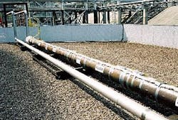
An existing run of stainless steel piping was used in the BPE test to transfer LNG from a storage vessel to the BPE vaporizer. The short run of piping for the LNG intake was prepared in a pipe-in-pipe configuration to simulate an LNG subsea pipeline, although the pipeline was aboveground and dry. Fig. 4 shows the test section.
There were several objectives of the test:
• Confirm feasibility of the configuration and the materials.
• Provide guidance for pipeline design.
• Obtain contraction characteristics of the configuration by measuring pipe contraction and strain.
• Obtain the overall heat transfer of the configuration by measuring the heat flux and temperature.
• Compare the results of the recorded data to analytical methods.
• Confirm the use of fiberoptic sensors as a nonintrusive method to monitor LNG pipelines.
• Obtain an understanding of LNG flow in pipelines.
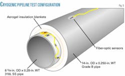
The test section consisted of a pipe-in-pipe configuration with the inner LNG product line being a 6 5⁄8-in. OD by 0.280-in. WT, Grade 316-L stainless steel pipeline. The outer casing pipe was a 14-in. OD by 0.250-in. WT, Grade B carbon steel pipeline.
Fig. 5 shows the test section configuration. The total length of the test section was about 42 ft. The test section was supported on steel supports that would allow the section to move during the test if required.
It was impossible to prepare metallic bulkheads on the test section as in the proposed new LNG design due to BPE restrictions on welding on the LNG product intake pipe. Therefore, the design bulkheads could not be tested. Strain measurements, however, were taken in order to evaluate the contraction and expansion that the test configuration would face if bulkheads were installed.
The test section was insulated with 2 in. of a high-performance aerogel insulation that was provided by Aspen Aerogels Inc. The insulation material was in a blanket form that allowed the material to be installed easily around the inner stainless steel line by wrapping the blankets and securing them together with tape.
Two blankets achieved the total insulation thickness. Each blanket contained several layers of 0.25-in. thick insulation mats arranged in an overlapping pattern and contained within an outer wrapper that allowed each section to be completely sealed when wrapped, as the blankets were preformed for the pipeline diameter.
The result was an insulation that was firm to the touch and wrapped snuggly around the inner pipe. The insulation was precut and prepared to allow installation between nonmetallic spacers that were placed around the inner pipe.
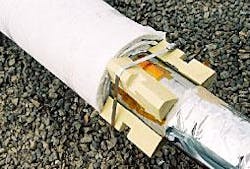
Spacers, or centralizers, were secured to the inner pipe to ensure that the outer casing pipe could easily slip over the insulated inner pipe and keep the inner pipe centralized within the configuration. Each spacer consisted of four “feet” that were strapped together with stainless steel banding. Fig. 6 shows the spacers being temporarily assembled adjacent the wrapped insulation. A heat flux fiberoptic sensor was installed under one of the feet to measure the effects of heat loss from the spacer.
Preformed insulation packets were placed around the spacers to ensure that the area was completely sealed. The only areas exposed to the inner and outer pipes were the spacer feet. Flotec Deepwater Services, Biddeford, Me., provided two types of material that were used for the spacers because the test was an evaluation of the materials to be used.
One heat-flux sensor was installed beneath the foot of one spacer in order to evaluate the insulation properties of the spacer as compared with the insulated pipeline section.
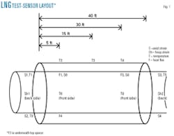
The test was conducted with flowing LNG; therefore, specialized fiberoptic heat-flux sensors were developed by Astro Technology Inc. (ATI) to measure the thermal efficiency of the insulation during this dynamic test. Additionally, ATI provided and installed Fiber Bragg Grating (FBG) fiberoptic sensors that measured temperature, pressure, strain, and contraction on the test piece. A total of 22 sensors were used on the test section (Fig. 7).
Leads from the sensors were collected in junction boxes, and three fiberoptic cables were run from the test section to a control and recording room in the LNG plant offices almost 1,000 ft from the test section. The signals were processed and recorded during the 5-day test event.
Instrumentation
Monitoring instrumentation is a key element in the present overall LNG pipeline configuration to address safety and security in the transport of cryogenic materials in a subsea environment.
The application of this monitoring technique is vital to a cryogenic pipeline, especially with respect to leak detection. A recent test by others of fiberoptic sensors for leak detection in oil and gas pipelines illustrates the importance of this technology.6
Fiberoptic sensors can provide real-time strain, temperature, vibration, and flow monitoring for subsea LNG pipelines. Fiberoptic sensors are attractive in these applications because of their multiplexing capability, immunity to electro-magnetic interference, ruggedness, and long-distance signal transmission ability.
Feasibility of using fiberoptic sensors offshore has been demonstrated through full-scale riser deployment in the Gulf of Mexico.5 Here are some of the key features of fiberoptic sensors:
• Lightweight and small.
• Rugged with a long life; sensors last indefinitely.
• Inert and corrosion resistant.
• Little or no impact on the physical structure. Can be embedded or bonded to the exterior.
• Compact electronics and support hardware.
• Easily multiplexed, significantly reducing cost and topside control room power and space.
• High sensitivity.
• Multifunctional-they can measure strain, temperature, pressure, and vibration.
• Require no electric current and are immune to electromagnetic interference.
• Safe to install and operate around explosives or flammable materials.
Fiberoptic sensors recently have monitored cryogenic temperatures of the LNG pipeline test section discussed here. Temperature, strain and heat flux were successfully demonstrated. This was also the first time heat-flux sensors-developed originally in the US space program-have been used in the oil and gas industry for cryogenic applications.
Results
Five days of data were collected during the partial and full flow conditions, and the information has been useful in understanding the dynamics of LNG flow in a cryogenic pipeline and in defining the requirements and details of the pipe-in-pipe configuration.
The pipeline test revealed the advantages of the nanoporous aerogel insulation, as it proved to have high thermal insulating characteristics. It allows a smaller thickness as compared with conventional insulation systems, resulting in a reduction in the outer diameter for the pipe-in-pipe configuration. It was easy to install during the test section preparation.
An additional advantage was the test insulation. It is considered to be hydrophobic, in that the molecules of water are larger than the pore space of the insulation. It is an ideal insulation in marine environments because it sheds or repels water.
There is no need for a water stop required in common insulation systems because the aerogel insulation is contained within a Tyvek outer wrapping, and the aerogel is by definition hydrophobic. Inspection of the insulation following the test also revealed that the insulation showed no physical changes as a result of the cryogenic test.
The pipeline test also revealed the advantages of the nonmetallic spacers-centralizers. The spacers adequately supported the pipeline section and prevented the insulation from contacting the casing pipe. No damage or effect was noted after the test to the two types of material from the cryogenic temperatures.
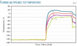
Fig. 8 shows four LNG pipe temperatures from the LNG test in Georgia. The data have been compensated for sensor nonlinearity based on the cryogenic benchmark test performed at NASA. This sample chart gives a good indication of the variations in temperature readings during changing flow conditions.
When there is full LNG flow in the product line, the temperature measurements are consistently the same. Then when the flow is interrupted, there is a difference in temperature readings with the sensors detecting a “warming” in the line, followed by a time of partial flow. The temperature recordings on the chart are for sensors on the product pipeline.
Although temperature readings on the external casing pipe are not shown on the attached chart(Fig. 8), the temperature of the casing pipe during full and partial LNG flows followed the general temperature profile of the ambient air, with some warming detected from the sun, on days with sunshine.
Detailed analyses of the temperature and strain measurements are in progress. Analysis of heat flux data will be performed after benchmark tests of these sensors.
Sensor benchmarking
Subsequent tests of the fiberoptic sensors in a controlled test chamber down to -300° F. confirmed the baseline measurements and verified that the monitoring sensors are capable of performing in cryogenic temperatures. Astro Technology Inc. conducted a series of tests on its Fiber Bragg Grating (FBG) fiberoptic sensors that were used in the Phase 1 LNG pipeline test in Georgia.
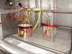
These tests were performed at the NASA Johnson Space Center test facilities under the NASA/ATI Space Act Agreement. The chamber used was able accurately to control down to cryogenic temperature (-300° F.). Fig. 9 shows the benchmark test set-up.
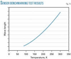
The FBG sensors used in the Phase 1 test are generally expected to have a linear temperature response. This does not hold true when the temperatures approach the cryogenic region. At colder temperatures, the FBG response is less as the temperature drops.
The test characterized the FBG temperature response down to -300° F. This test used a short section of the actual pipe from the Georgia LNG test as well as a piece of INVAR. INVAR was used because it has a very low coefficient of thermal expansion. This property was intended to separate and determine the different coefficients within the FBG response equations.
Both the pipe section and the INVAR material were instrumented with multiple FBG sensors, in both the strain and temperature reading configurations. The two pieces were also instrumented with thermocouples and platinum RTD sensors. The test was run in a thermal chamber with a temperature profile from +150° F. to -300° F.
The rate of temperature change during the test was kept low to ensure isothermal conditions on the sample. To further reduce errors, the outside surfaces of the samples where insulated to reduce temperature gradients.
All of the FBG sensors operated successfully across the full temperature profile. This test generated a plot of FBG wavelength vs. temperature. Fig. 10 shows the wavelength vs. temperature profile. This temperature curve corrected the nonlinear response of FBGs when used at cryogenic temperatures. Equations were derived that describe the behavior at cryogenic temperature.
Applications
The Phase 1 test used an available flowline size of 65⁄8-in. OD, which is equivalent to the type of product piping used in an LNG facility. The test verified that the insulation and spacer materials used are suitable for this application without modification. The tests indicated that a thin stainless steel outer jacket would be adequate cover for the insulation in a plant facility or offshore topsides LNG application.
For major loading-line applications, however, the product pipeline size would be on the order of a 30-in. OD pipe, and for a subsea application, an external casing pipe would be required. For long runs of offshore loading lines, it will be necessary to build configurations that include bulkheads to constrain the pipe-in-pipe to account for the expected contraction-expansion that would be expected. Analysis has indicated that the bulkhead design would be adequate for the larger scale up, but this would require a future test to confirm the design in cryogenic conditions.
Future tests
A series of further tests is planned. One involves more fiberoptic-sensor benchmarking, and the other tests are a component test and a full-scale test.
Although benchmark tests have been completed for the FBG sensors used for the temperature and strain measurements, the heat-flux sensors have not yet been benchmarked.
Future tests for the heat-flux sensors are being planned at the same facility where the previous benchmark tests were performed.
A fatigue test of the bulkhead configuration under cryogenic temperatures is also planned. This test may also be conducted at the same site where the previous cryogenic benchmark tests were conducted.
The test would be used to verify the analytical results of the metallic bulkhead design and to evaluate the bulkhead properties and characteristics of a nonmetallic design.
Following these tests, a full-scale test with the design bulkheads is planned to illustrate the capabilities of the configuration and to further verify the monitoring capabilities of the fiberoptic monitoring system.
Acknowledgments
The authors thank Fluor Inc. and Astro Technology Inc. management for the permission to publish this article. ✦
References
1. Merrill Lynch, “Global LNG: a High Growth Market,” Global Octane, Chapter 9, Oct. 23, 2002.
2. Society of International Gas Tankers & Terminal Operators, LNG Operations in Port Areas-essential best practices for the industry, first edition, 2003.
3. Sandia National Laboratories, Report SAND2004-6258, “Guidance on Risk Analysis and Safety Implications of a Large LNG Spill over Water,” December 2004.
4. De Baan, J., Krekel, M.H., and McCall, M.M., Leeuwenburgh, R., “Offshore Transfer, Re-Gasification and Salt Dome Storage of LNG,” OTC 15301, Offshore Technology Conference, Houston, May 2003.
5. Prescott, Neal, and Brower, David V., “Real Time Subsea Monitoring and Control for Pipelines,” Subsea Rio, June 2004.
6. Walker, Ian, et al., “Fiber Optic Leak Detection,” OTC 15360, Offshore Technology Conference, Houston, May 2003.
Based on a presentation at the Offshore Technology Conference, May 2-5, 2005, Houston.
The authors
Clifford Neal Prescott is director, subsea and deepwater technology at Fluor Corporation’s Upstream SBL, Energy & Chemicals unit in Sugarland, Texas. He holds a BS in civil engineering from the University of Texas in Austin (1965) and has completed the business management program at Rice University in Houston (1986).
Jeff Zhang is principal design engineer for flow assurance at Fluor Corporation’s Upstream SBL, Energy and Chemicals unit in Sugarland, Texas. He previously worked as principal engineer for flow assurance at Technip-Coflexip, technical adviser for production and wells at Halliburton Company and as an engineer at Shell E&P Technology Company. Zhang holds a BS in mechanical engineering from the University of Science and Technology of China (1988), an MS in mechanical engineering from the University of Houston (1991) and a PhD in mechanical engineering from the University of Houston (1995). He is a member of SPE and MTS and is a registered professional engineer in Texas.
David Brower is founder and president of Astro Technology in Houston. He holds a BS degree in materials science and engineering from the University of Utah (1980).

