Loading pipe design improves boil-off gas management
Maksym Kulitsa
FSRU consultant
Odessa, Ukraine
David A. Wood
DWA Energy Ltd.
Lincoln, UK
A new LNG loading pipe design can use in-tank condensation to improve boil-off gas (BOG) management during ship-to-ship (STS) transfers. Part 1 of this article (OGJ, June 4, 2018, p. 77) described how in-tank condensation for additional BOG handling could be used at no incremental operating cost to improve STS. Part 2, presented here, lays out the conceptual design of a customized loading pipe able to fully utilize in-tank condensation while retaining the quality and simplicity of traditional LNG loading pipes. The concept is described for a membrane prismatic tank, although it could also be applied to Moss-type (spherical-self-supporting) tanks by including slightly more complex features.
The system has no wearing parts and is maintenance free, yet provides significant additional vapor condensing capacity, drawn from the in-tank vapor space. This self-balanced system provides valuable additional BOG handling capacity during STS transfers. It sometimes also can provide short-term additional BOG handling capacity during regasification, when excess pressure needs to be urgently handled to avoid disposing of gas in the gas combustion unit or steam dump.
Design
The concept’s basis is its ability to suck tank vapor by the Venturi effect into the filling pipe and deliver it to the tank bottom, where LNG is most subcooled and able to recondense the largest quantity of such vapor. MAXO-pipe, the system used, is an in-tank loading-filling pipe that replaces the existing standard filling pipe, providing additional BOG-handling capacity for very-low, if any, incremental operating costs.
A key advantage of the concept is its lack of complex or wearing parts, allowing for easy installation on newbuild floating storage and regasification units (FSRU) and easy retrofit to the pipework of existing FSRU. It aims to maintain the prevailing cargo tank pressures at close to saturated vapor pressure (SVP) on FSRU during STS transfers at high flow rates, which would otherwise be compressed to a high tank pressure (OGJ, June 4, 2018, pp. 74-81). Recondensing may be manipulated during operations to reduce its rate in certain conditions, e.g. when the LNG level is low. This avoids large, warm LNG plumes emerging at the LNG surface without sufficient mixing with the rest of the colder LNG bulk, which would diminish the technique’s benefits.
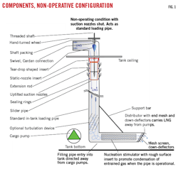
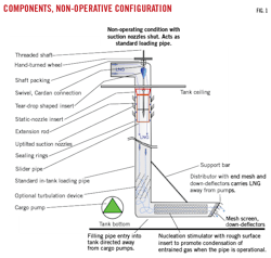
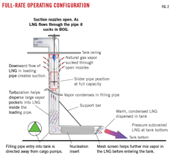
The system allows higher flow rate STS transfer and effective packing of the tank vapor space, both of which lead to an increased capacity for recondensing vapor. Its principal features (Figs. 1-2) include:
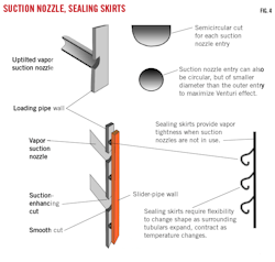
• Up-tilted vapor-suction nozzles. Tubular pipes of much smaller diameter than the tank filling line are welded to the body of the filling line close to the tank ceiling. Inlets to the filling line have a smaller diameter than the nozzles’ diameters protruding into the tank to avoid suction disturbances. Semicircular entry points are the easiest way to achieve this and prevent flooding the nozzle with liquid. The number and size of the suction nozzles can be adjusted to optimize performance.
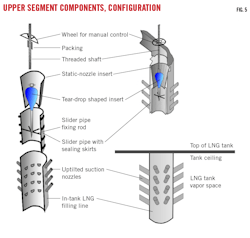
• Slider pipe. This moveable section of pipe, slightly smaller in diameter than the filling line, is placed within the filling line. Its size allows it to move freely without sticking inside the filling line. The freedom of motion needs to be sufficient to account for contraction-expansion (due to temperature fluctuations) and allow small packing and sealing rings to be placed between the slider pipe and the main pipe. The slider pipe provides the system with the flexibility to vary suction by closing some or all nozzles.
The ability to completely close all nozzles is important as it guarantees efficient standard pre- and post-dry-docking operations, such as gassing up and inerting. Absent full closure, such operations would consume significantly more LNG or inert gas. A closed slider pipe transforms MAXO-pipe into a simple loading line. A variably-open slider pipe provides recondensing capacity control by varying the number of operating nozzles, which in turn controls the quantity of vapor entrained by liquid flow into the tank.
• Sealing rings, skirts. These are hollow- or labyrinth-type components fixed to the slider pipe in several separate rows to improve sealing. These rings need to be made of material suitable for cryogenic-temperature service and able to provide acceptable vapor tightness. The vapor tightness does not need to be absolute, as minor seepage of vapor or liquid between the slider pipe and the filling pipe is not a problem. During gassing up or inerting operations minor seepage may be disregarded as the main flow of gas delivery effectively creates a piston effect while changing the tank’s atmosphere.
• Threaded shaft, extension rod with cardan connections and expansion joint (universal joints). This arrangement is a simple and cheap way to position the slide pipe within the main pipe. Cardan and expansion joints must compensate for possible deformations introduced by expansion-contraction in varying cryogenic conditions. The threaded shaft is packed on top of the outside section of the loading pipe to be leak-free.
• Liquid velocity control (tear-drop shape). The extension rod is fitted with an inverted teardrop-shaped component to finely adjust liquid velocity. When the slider pipe is moved downwards, the inverted teardrop component enters and narrows the aperture of the static insert nozzle, increasing liquid velocity and the magnitude of the Venturi effect.
• Static insert nozzle. This provides a fixed small reduction in the loading pipe diameter to further enhance suction effect by increasing liquid velocity. The diameter reduction of the insert nozzle aperture needs to be small enough to not significantly increase back-pressure during loading.
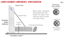
• Turbulation device (optional). A fluid mixing enhancer consisting of rigid spiralling blades is positioned upstream of the distributor to ensure vapor and liquid are well mixed by the turbulent flow within the filling line. The device breaks up any large vapor pockets that might form in the filling pipe, thereby enhancing vapor condensation. It is non-essential but can improve performance in certain conditions.
• Filling pipe outlet into cargo tank and distributing horizontal section. By directing and extending the bottom outlet of the filling line into the cargo tank horizontally, away from the pumps, the filling pipe avoids vapor and warm LNG interference with the pumps. Absent such positioning there is a risk that vapor pockets could enter the pumps and lead to cavitation or impede performance.
The horizontal orientation of the filling pipe entry is distinct from the vertical entry of the traditional loading pipe. A short-distributing horizontal section, jetting the LNG into the central-base of the tank, plus downward deflectors at pipe-end entry to the bottom of the tank, maximize fluid spreading over a larger area.
• Nucleation surfaces within the distributor. Placing nucleation sites in the distributor’s internal section (i.e., divots to create a non-smooth surface) enhances condensation of the entrained BOG. It is therefore recommended that the internal surface of the distributor be designed to incorporate nucleation surfaces. A cross-wire or multiple-cross insert also can be included to provide additional nucleation surfaces.
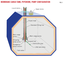
The system requires no additional pipe to be installed on the pump tower and is fully compatible with existing pump tower designs and pipework configurations (Fig. 3). Figs 4-6 provide design details for the system that enable it to be easily fitted, or retrofitted to existing FSRU vessels.
The design fully assures vapor delivery and in-tank recondensing of vapor transported to the base of the tank. It also includes the flexibility to achieve variable condensation capacities that can be easily regulated by adjusting the suction from zero to the maximum prevailing capacity. When the suction nozzles are fully shut with the slider pipe, then the system operates as a traditional filling line with negligible constriction caused by the insert nozzle, turbulation device, and nucleation inserts. Moving the slider pipe downwards opens the uppermost suction nozzles initially at low suction rates.
The further down the slider pipe is moved, the more suction nozzles are opened, increasing suction. At the same time the inverted teardrop-shaped component enters the insert nozzle aperture and increases liquid velocity, enhancing suction by the Venturi effect. The condensing capacity, determined by prevailing tank and STS conditions, also can be regulated by adjusting the number of suction nozzles in service at any given time and the size of the insert aperture, making it easy to fine tune suction to suit prevailing FSRU operating conditions. The sliding pipe is moved by a manually-operated valve arrangement with a long-threaded shaft incorporating a cardan and expansion joint to compensate for cryogenic temperature deformations (Fig. 5).
Rollover issues
MAXO-pipe cannot itself create stratification in an LNG tank, as the upwelling turbulent flow of warmer LNG or uncondensed BOG-created turbulence effectively works against stratification formation. Stratification is often created during STS transfer, typically when loading a new heavy cargo into a light LNG heel cargo. The turbulence caused by the system’s operations is localized, so stratification is likely to be prevented only if the heel cargo is very small. Unlike traditional loading pipe, the system-generated turbulence always reduces the top LNG layer’s volume. In optimum conditions it prevents stratification from forming.
If stratification occurs during STS, it is appropriate to run the system at full capacity until the tank is one-third full. At that point it would be prudent to check the temperature of the LNG in the bottom layer. If the temperature has risen significantly and the SVP of the LNG in the bottom layer is approaching the tank’s maximum allowable relief-valve setting (MARVS), system operation should be slowed or temporarily halted.
Once stratification occurs and the interface layer is moved upward, the condensing BOG and resulting warmed LNG at the tank bottom will only be dispersed within the bottom LNG layer, ultimately enhancing the strength of Rollover Stage 3 (OGJ, June 5, 2017, p. 80).
Warming of the LNG in the bottom layer is likely to be faster, because the same quantity of condensed BOG is heating a smaller mass of LNG, the top-layer LNG mass effectively excluded from bottom-layer circulation during stratification. Consequently, while stratification conditions prevail, particularly with a low mass in the lower LNG layer, it is not appropriate to transport BOG to the bottom of the tank.
In such conditions, the upper LNG layer typically produces less BOG, which means that less additional handling capacity is required. In some stratification situations MAXO-pipe can be run at reduced capacities to control bottom layer heating. When stratification is not destroyed initially by the system’s full flow operation, the heating of the bottom layer may need to be inhibited by reducing suction capacity, increasing it gradually only as the bottom layer’s LNG mass increases. While stratification prevails, BOG from the tank is naturally reduced,1 generally requiring less BOG handling capacity. Running the system in such conditions does not cancel out other rollover mitigating and prevention measures (OGJ, June 5, 2018, pp. 74-81).
STS transfers happen quickly and the condensed masses of BOG moved by the system in such operations (versus the total mass of LNG in the tank) are relatively small. Consequently, bottom-layer heating is likely to be limited and unlikely to cause rollover issues. At the start of an STS transfer it is therefore best to transfer liquid at high rates, increasing to full rate as soon as possible with the pipe system also running at full capacity. Non-condensed BOG will create significant turbulence and mechanical mixing in the region of the tank affected by pipe operations, typically reducing the volume of the top LNG layer and sometimes preventing stratification.
Operational advantages
The system is self-balancing and, to an extent, self-regulates its capacity to condense vapor, depending on prevailing pressure and LNG mass. It also provides sensitive capacity control with the ability to vary suction at any moment. Vapor sucked into MAXO-pipe is either fully or partly condensed. Any vapor not condensed is at least cooled and shrunk, with a positive impact on tank pressure.
Tank loading operations drive recondensing, eliminating the need for additional energy (i.e., no compressors, pumps, etc.). No extra fuel is consumed in realizing this recondensing, in contrast to traditional recondensing systems.
The system is designed specifically to modify existing loading pipe (retrofit) or is easily fabricated for new-build vessels to replace standard loading pipe. It therefore requires no additional penetrations of the tank dome or modifications to the tank or pump tower structure. It is almost static, of simple design, and involves no parts that display wear following extensive operations or require regular maintenance.
It is relatively cheap to construct and install. Due to its simple design, it requires no high precision fabrication, special materials, or complicated parts. Suction can be easily controlled by manipulating the number of suction nozzles in service, together with controlling liquid velocity by adjustments to the inverted teardrop component to suit prevailing conditions.
Transforming the system into a standard loading pipe configuration, such as would be required pre- and post-dry docking, requires little effort.
Enhancing mechanical mixing of new LNG and the heel when stratification starts to form by operating the system at maximum suction can reduce the upper LNG layer’s volume, or occasionally prevent stratification altogether.
Limitations
The system’s main limitation is the restricted time over which its benefits are achieved. It can only create suction and entrain vapor when a relatively large LNG flow is passing through it. It is therefore most efficient during STS transfers. It cannot sustain BOG condensation the way standard recondensing systems can and does not replace the need for traditional recondensing systems. The new system is likely to be less efficient at low liquid-transfer rates. There is a minimum flow rate required to drive the system efficiently.
While not part of an STS transfer, LNG could be recirculated by the main cargo pumps through the filling line to generate sufficient flow velocity to entrain BOG from a tank’s vapor space. But doing so would consume energy and heat the LNG, substantially reducing or negating the system’s positive tank-pressure control benefits. In certain conditions, however, the system can be used to provide some short-term benefits in BOG handling (e.g. peak shaving during high tank-pressure events not related to rollover), particularly with a large LNG mass in the tank.
The system has low condensing capacity in conditions when there is a small LNG mass in an FSRU tank (e.g., as STS transfer begins). There also will likely be a reduction in recondensing capacity towards the end of tank loading as the LNG in the tank reaches very high levels or LNG velocity through the loading pipe slows, causing a weaker Venturi effect.
All components must be able to withstand potential vibration damage.
The system provides the greatest potential benefits to FSRU with low MARVS (250-400 mbarg), and for those fitted with low-capacity recondensers (< 5 to 5.5 ton/hr) or no recondenser. Its simplicity, however, allows it to provide additional recondensing capacity and tank-pressure control for all types of FSRU.
Reference
1. Society of International Gas Tanker and Terminal Operators, “Guidance for the Prevention of Rollover in LNG Ships,” 1st Ed., 2012.
