PIPIP technology aids LNG transfer
The inherent design features of current pine-in-pipe-in-pipe technology allow LNG to be transferred both subsea and buried onshore safely and securely, with minimal risk to the environment. This ability is enhanced by an associated integrity monitoring system that provides rapid and sensitive leak-detection capabilities. ITP InTerPipe’s PIPIP technology received DNV’s Certificate of Fitness for Service in 2007.
Leaks are primarily detected by monitoring pressure in the annulus. Because the inner annulus is closed, arbitrarily small leaks can be detected via pressure measurement; the only variable being how much time is required. The leak-detection capability in the PIPIP system is orders of magnitude better than can be achieved with conventional leak detection. For example, a leak of 0.002 cu m LNG/hr (0.00004% of the flow rate) can be detected in about 18 hr.
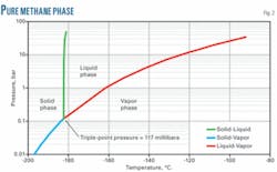
The case study presented shows the ability to detect leaks when about 40 l. of LNG had leaked into the annulus. Since the inner annulus pressure is less than the triple point of methane (117 millibara), pure methane cannot exist as a liquid in the annulus. Leaks will consist primarily of a mix of vapor and solid methane, with the solid methane subliming after continued contact with the inner pipe.
Leak location can be detected by fiber optic methods for all leaks large enough to affect the temperature of the intermediate pipe. Annulus pressure monitoring will detect a small leak more quickly than the fiber optic temperature monitoring. The fiber optic method will detect large leaks more quickly. A leak in the intermediate pipe can be distinguished from a leak in the inner or outer pipes by either the fiber optic measurement or the rates at which the pressures of the inner and outer annuli change.
Background
LNG projects involve large capital investments and all product must pass through a pipeline to and from the ships. This requires reliable pipelines, particularly if they are to be subsea and, ideally, accurate, reliable pipeline-integrity monitoring systems. This article discusses the inherent safety of an LNG PIPIP design as well as leak-detection thresholds and times.
Pipe design
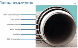
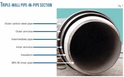
ITP undertook a formal technology review process for its LNG pipe technology, culminating in a DNV Certificate of Fitness for Service (OGJ, May 21, 2007, p. 62). Fig. 1 shows the multi-walled LNG pipe.
Its key features include:
- A 36% NiFe inner pipe with a coefficient of thermal expansion ten times lower than that of stainless steel. The low CTE minimizes expansion and contraction of the pipeline, mitigating the need for expansion loops or bellows. LNG carriers have used 36% NiFe for membranes for more than 40 years.
- Patented microporous insulation, used in subsea pipelines since 1998. The insulation consists primarily of silica and titanium dioxide. Installed in an LNG pipeline, it provides an overall U-value of 0.131 w/sq m-°C. using only 40 mm of insulation. The insulation also has high mechanical compressive strength and can support the weight of the filled LNG pipe, eliminating the need for centralizers. The insulation can tolerate temperatures up to 900º C., allowing the intermediate and outer pipes to be welded directly over the insulation without damaging it. Field joints can thus be insulated with the same procedures as running pipe.
- An inner annulus, typically continuous along the entire pipeline length. The inner annulus operates at reduced pressure. The reduced pressure increases the thermal performance of the insulation, eliminates inner annulus conditions which could allow methane to exist as a liquid (only solid and vapor can exist), and acts as a straightforward, robust, and sensitive leak-detection system.
- An intermediate pipe designed to handle collapse, providing additional protection from external damage and the environment. Depending on specific application, the intermediate pipe’s design can provide double pressure containment to prevent release of the LNG into the environment.
- An outer annulus with the pressure continuously monitored.
- A carbon steel outer pipe designed for collapse and prevention of buckle propagation, and featuring anticorrosion coating and cathodic protection for a subsea pipeline.
The triple-wall pipe design provides two barriers of protection from accidental external damage in a subsea application. Onshore applications would typically use a double-walled design. Bulkheads connect the inner and intermediate pipes and the intermediate and outer pipes. These bulkheads form sealed inner and outer annuli. Field joints consist of straightforward butt welds for all pipes (inner, intermediate, and outer).
A pipeline integrity-monitoring system based on continuous pressure monitoring of both annuli detects leaks and differentiates between leaks in any of the three pipe walls, providing leak detection orders of magnitude more sensitive than conventional pipeline integrity monitoring systems. Including a fiber optic system in the outer annulus can provide secondary leak detection and location. The fiber optic also provides the temperature of the intermediate pipe along the entire length of the pipeline at 1-m intervals.
A pipeline integrity-monitoring system similar to the one described here recently quickly verified the integrity of Camisea LPG PIP pipelines in Peru after a magnitude 8 earthquake centered near the pipeline installation
Methane
The inner annulus of the PIPIP system is maintained at a reduced pressure (i.e., below atmospheric). Fig. 2 shows a phase diagram for pure methane. Maintaining pressures below the triple-point pressure of 117 millibara prevents formation of liquid methane. Instead, when the LNG flashes across the leak to the reduced-pressure environment in the inner annulus, the final phase will be either vapor, or a mix of vapor and solid methane. Thus, as long as the inner annulus pressure remains below 117 millibara, no liquid methane can exist.
The LNG’s composition, however, affects this process. Since the triple-point pressures of ethane, propane, and butane occur at much lower pressures, a small portion of any leak may be liquid depending on the actual composition of the LNG.
Preventing liquid methane from entering the inner annulus limits the likelihood that it could accumulate at the bottom of the intermediate pipe. Such accumulation would result in highly localized cooling and, for PIP or PIPIP designs using a carbon-steel intermediate or outer pipe, a drop below the design temperature of the carbon steel pipe.
Since only gas and solid are present, however, the solid will remain local to the leak (it will eventually sublime into a gas phase) and the gas phase will diffuse into the annulus. If only gas is present, it will also cool the intermediate pipe, but being much more diffuse will do so in a less localized manner.
Integrity monitoring
The PIPIP design provides a rapid, sensitive, and accurate leak-detection system. Both annuli are continuous and the pressures in the annuli are continuously monitored. Since the annuli are closed and the pressures in the two annuli are different (<117 millibara in the inner annulus and about 3 bar in the outer annulus), any leak results in a pressure change in one or both annuli, allowing the leak’s detection. A fiber optic in the outer annulus can also detect the location of any leak in the inner pipe that poses a risk to the intermediate pipe.
Case study
Main parameters governing design of the PIPIP were:
- Length, 10 km.
- Total flow rate, 10,000 cu m/hr.
- Number of pipelines, two.
- Maximum water depth, 15 m.
- Ambient temperature, 25º C.
- Burial depth, 1 m to top of pipe.
With these parameters, preliminary design of the PIPIP resulted in the following system:
- Inner pipe, 30-in. OD (36% nickel, designed for 30-bar internal pressure).
- Intermediate pipe, 36-in. (carbon steel, designed for collapse).
- Outer pipe, 40-in. (carbon steel, designed for collapse-buckle propagation).
- U-value: 0.12 w/sq m-ºC., based on the inner pipe ID.
- Outer pipe temperature, 16º C.
Maximum operating pressure equals 9 bar.
Leak rates
An engineering critical assessment performed in accordance with BS7910 Level 2 for 36% NiFe pipe used the calculated membrane hoop, longitudinal and bending stresses for the operating temperature and maximum pressure. The ECA showed that flaw sizes within DNV’s acceptance criteria for radiography were stable over the design life of an LNG project. The maximum allowable flaw sizes were therefore used as the basis for calculating crack widths. The calculated crack widths proved consistent with reports of crack widths in stainless steel pipe from the nuclear industry, where the mean width for thermal and mechanical fatigue cracks are 15 and 8 µm, respectively.
Knowing the crack opening area, the upstream and downstream pressures, the upstream temperature, and upstream composition does not, however, allow calculation of the leak rate. The roughness and depth of the crack also need to be determined. The crack likely does not run exactly perpendicular to the surfaces of the wall and so will have a greater depth than the wall thickness.
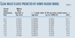
Leak-rate calculation is enormously complex, involving multiphase flow with interfacial mass, heat, and momentum transfer; interactions with a rough wall; multiphase equilibria; and critical flow. A simplified approach recognizes that the predicted leak rate will be conservatively high and uses the Henry-Fauske model to predict leak rates.
This model accommodates critical flow, which is to be expected here due to the combination of low pressure, multiphase flow through the crack, and subcooled liquid upstream. The model’s major shortcoming in the current context stems from its assuming that friction with the walls is negligible relative to pressure gradient and momentum effects. This assumption is completely appropriate for the modeling of high-velocity flows through orifices and converging nozzles, as recommended by the authors, but friction will obviously have a greater effect in flow through an 18 µm-wide crack.
The Henry-Fauske model stands validated against multiple data sets, including cases with subcooled liquid nitrogen flowing through nozzles where the flow is critical and the throat condition is liquid-vapor, making it appropriate for subcooled methane. The lack of any wall friction, however, will yield conservatively high leak rates.
Table 1 gives the results of Henry-Fauske calculations for a range of inner pipe (upstream) pressures. Throat (critical) pressures are 200-400 millibara. Throat pressures above the triple point yield a mixed vapor-liquid equilibrium condition. The calculated crack opening area of 0.18 sq mm yields a predicted maximum leak rate of 0.027 × 0.18 = 0.005 kg/sec; equivalent to 0.04 cu m LNG/hr or 16 cfm. Leak rates ranging from 0.005 to 0.04 cu m LNG/hr provided the basis for analysis.
Leak detection
Pipeline leak-detection systems typically rely on pressure and flow measurements to infer the presence of a leak. Ultrasonic or other direct-detection mechanisms can also detect leaks. Each of these methods has its own leak rate threshold, below which a leak cannot be detected. The closed inner annulus of this PIPIP pipe, however, allows detection of arbitrarily small leaks by pressure measurement; with the time required becoming the only question.
The time required to detect a leak via measurement of the inner annulus pressure depends on:
- Size of the leak.
- Inner annulus pressure before the leak.
- Accuracy of the inner annulus pressure measurement.
- Location of the leak (distance from the ends where the pressure measurement is made).
- Pressure drop in the annulus between the leak and the end of the pipeline.
The gauges specified for annulus-pressure monitoring on the ITP LPG pipeline in Peru provide the basis for pressure measurement accuracy. The pressure measurement gauges are accurate to ±6 millibar, up to 1,200 millibara. This gauge is sufficient, but more accurate gauges are also available.
Detection time
The elevated vapor mass created by a leak in the inner pipe causes pressure in the inner annulus to increase. The ±6-millibar accuracy of the gauges makes a 15-millibar increase in the pressure sufficient to detect a leak.
Two methods have calculated the time required to detect a 15-millibar increase in pressure as a function of leak size. The first is a simplified method, ignoring any pressure drop resulting from flow in the annulus and simply calculating the amount of methane necessary to increase the pressure by 15 millibar.
This proves quite easy (and independent of the starting pressure), since fluid in the annulus is an ideal gas. Once the amount of methane needed is known, dividing by the leak rate yields detection time, independent of leak location.
The second method accounts for pressure drop in the annulus; that the pressure at the leak will be higher than at the ends of the pipeline, where it is measured. The leak is always assumed to occur at the point farthest from the pressure measuremens, as this requires the longest time to detect.
Gas leaks in the annulus stemming from a leak result in laminar flow. Analysis of the problem as pseudosteady state is also assumed. The radial velocity profile adjusts quickly to changes in pressure and flow. A momentum balance for the flow in the annulus then provides a relationship between the volumetric flow rate (Q) and the pressure gradient (Equations 1-3).
These equations represent the standard solution for laminar flow in an annulus, with correction Fc applied for eccentricity of the inner pipe. Integrating the standard solution around the circumference of the annulus, treating κ as a function of angular position determined by the geometry of the eccentricity, determines Fc.
Since the mass flow rate consists simply of the product of the volumetric flow rate and density, and the density is related to the pressure via the ideal gas law, the momentum balance can be written as shown in Equations 4-6.
A mass balance on a section of the annulus (including the void space in the insulation) yields Equation 7.
Combining the momentum and mass balances provides the final equations to be solved (Equations 8-9).
A semi-implicit technique in Mathcad solves the partial differential equation numerically. A variable-size mesh in the axial direction uses fine discretization close to the leak and coarser discretization far from the leak. The inlet boundary condition consists of a fixed mass flow rate (the leak rate) and the outlet boundary condition is no flow (the outlet is closed).
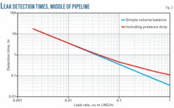
Fig. 3 shows the times required to detect a leak as a function of leak size. For leak sizes of interest, <0.04 cu m LNG/hr, the simplified calculation method provides a good estimate of detection time since the pressure drop becomes progressively less important for small leaks.
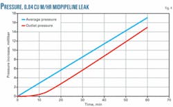
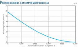
Fig. 4 shows the average annulus pressure and the outlet pressure (where the measurement is made) as a function of time. Fig. 5 shows the pressure profile at the time a leak would be detected from outlet pressure monitoring.
The closed, low-pressure annulus makes the leak-detection capability in the PIPIP system orders of magnitude better than can be achieved with convectional leak-detection systems. For example, a leak of 0.002 cu m LNG/hr, or 0.4 ppm relative to the flow rate, can be detected in 18 hr.
Differentiating leaks
By itself, the pressure measurement in the inner annulus cannot distinguish between a leak in the inner pipe and a leak in the intermediate pipe, since both will result in the inner annulus pressure rising. Two methods are available to distinguish the different leaks.
If the fiber optic measurement shows a decrease in temperature in a localized area, a leak of the inner pipe is indicated; a leak from the outer to the inner annulus has a negligible effect on the temperature of the outer annulus and the intermediate pipe wall where the fiber optic is located.
A leak in the intermediate pipe, however, will cause the pressure in the outer annulus to drop, which will be detectable. Since the fluids in both annuli are ideal gases at about the same temperature, the pressure change in the outer annulus is related to the pressure change in the inner annulus simply by the ratio of the volumes of the two annuli.
If the leak is in the intermediate pipe, the inner annulus pressure will increase at about 60% of the rate that the outer annulus pressure decreases (Equation 10). A gas detector connected to the inner annulus provides a further possibility for distinguishing between inner and intermediate pipe leaks. Detection of methane would indicate an inner pipe leak. This method would generally require use of vacuum pumps to pull gas in the inner annulus through the detector.
Temperature monitoring
The expected accuracy of fiber optic measurement is ±1º C. Given variations in soil coverage and ambient water temperatures, a local decrease of 4º C. indicates a leak. Since fiber optic measurement resolution is 1 m, the temperature 0.5 m from the leak provides the measure of when a leak is detected by the fiber optic.
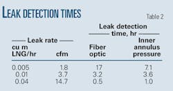
A method was developed to predict the temperature of the intermediate pipe as a function of time and distance from the leak. This model was used to predict temperature profiles along the intermediate pipe for various leak rates. Table 2 summarizes these results. Leak-detection times via pressure measurement included in the table allow comparison. For leaks below about 0.01 cu m LNG/hr, pressure monitoring will detect the leak first.
Bibliography
Cumblidge, S.E., Anderson, M.T., and Doctor, S.R., “An Assessment of Visual Testing,” NUREG-CR-6860, November 2004.
Henry, R.E., and Fauske, H.K., “The Two-Phase Critical Flow of One-Component Mixtures in Nozzles, Orifices, and Short Tubes,” Journal of Heat Transfer, pp. 179-187, May 1971.
Lemmon, E.W., McLinden, M.O., and Huber, M.L., “Reference Fluid Thermodynamic and Transport Properties,” NIST Standard Reference Database 23, Version 7.0, 2002.
Manglik, R.M., and Fang, P.P., “Effect of Eccentricity and Thermal Boundary Conditions on Laminar Fully Developed Flow in Annuluar Ducts,” International Journal of Heat and Fluid Flow, Vol. 16, No. 4, pp. 298-306, August 1995.
Norris, D.M., and Chexal, B., “PICEP: Pipe Crack Evaluation Program,” EPRI NP 3596-SR, 1987.
Ozisik, M.N., Heat Transfer: A Basic Approach, 1985.
Paul, D., Ghadiali, N., Wilkowski, G., Rahman, S., and Krishnaswamy, P., SQUIRTSeepage Quantification of Upsets in Reactor Tubes, Computer Program, Battelle Memorial Institute.
Perry, R.H., and Chilton, C.H., Chemical Engineers’ Handbook, Fifth Edition, 1973.
The authors
Michael Offredi ([email protected]) is LNG manager for ITP InTerPipe SA, and has been involved as project engineer and project manager in the engineering, fabrication, construction, and installation of deepwater lines and cryogenic pipe-in-pipe systems for the last 11 years. He was the ITP project manager for the Camisea pipe-in-pipe project in Peru, which included onshore buried and subsea refrigerated LPG transfer lines. He also headed development and qualification of the ITP LNG cryogenic pipe, including the full-scale test program supported by several gas majors.
Trent Brown ([email protected]) is engineering manager of ITP InTerPipe, Inc. Previously he was a cofounder and coowner of Multiphase Solutions Inc. As a principal consultant at MSI he developed models for multiphase flow in pipelines and phase equilibria including hydrates and wax and performed flow assurance studies. Prior to MSI, Brown worked for Conoco Inc. in production technology. He holds a BS, MS, and PhD in chemical and petroleum refining engineering from the Colorado School of Mines. He is a member of SPE.
Vicki Niesen ([email protected]) is president of ITP InTerPipe Inc., Houston. Previously she was a cofounder and coowner of Multiphase Solutions Inc. As a principal consultant at MSI she performed numerous conceptual, FEED, and operational modeling studies of wells, flowlines, risers, and export gas and oil pipelines. Prior to MSI, Niesen worked for Conoco Inc. in production technology and for the National Institute of Standards and Technology. She holds an MS and PhD in chemical and petroleum refining engineering from the Colorado School of Mines. She is a member of SPE.
