LP model uses line-pack to optimize gas pipeline operation
The compressibility of natural gas allows the use of line pack to compensate for fluctuations of gas demand. On the basis of forecast consumption, a linear-programming model can yield a plan for optimal flow rate of a gas pipeline.
This model allows demand fluctuation to be satisfied with a minimum of energy consumption. Using this model requires the definition of maximum storage capacity as well as a permanent control algorithm of its evolution over time.
System configuration
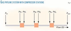
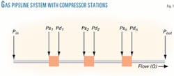
Transporting natural gas by pipeline from producing fields to customers requires a given number of compressor stations (CS) to maintain the pressure necessary for gas flow (Fig. 1).
Compressor stations may consist of a single turbo compressor (TC) or a set of identical or different turbo compressors arranged in parallel or series. The high operating costs of transmission pipelines, compared with distribution systems, motivates this study of transmission systems. The flow rate at the end of pipeline varies, depending on demand.
A considerable amount of the transported gas is consumed as fuel for the pipeline. Depending on the number of compressor stations, the fuel consumption represents between 5% and 10% of the transported flow rate.2 3 Reducing the cost of transportation, a major preoccupation of operators, consists essentially of decreasing fuel consumption.
For this purpose, the linear-programming model described here has been used to generate an approach for optimal planning of a gas pipeline's operating system, taking line pack into account.
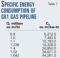
A simulation of the model treats the Algerian gas pipeline GK1 Hassi R'mel–Skikda (Table 1).
Mathematical model
Calculating head losses requires the following assumptions:
The flow is steady state and isothermal.
The friction factor and compressibility factor vary little from average values.
The variation of the kinetic energy is negligible compared with friction forces.
Therefore, Equation 1 (see accompanying box) gives head losses of a pipeleg. Equation 2 yields the calculation of the temperature profile along the pipeleg; Equation 3 defines the actual power required.
Click here to view Equations
Gas turbine performance data are based on International Standards Organization (ISO) conditions which are sea-level operation at an ambient temperature of 15° C. and 0 psi inlet and exhaust pressure drops.
Gas-turbine performance is usually stated at baseload operation (continuous operation for 7,600 hr/year or more) and includes power rating, heat rate, and specific fuel consumption based on the lower heating value of the fuel, air flow, turbine design speed, compression ratio, and turbine inlet, and exhaust temperatures.
Performance ratings expressed at ISO conditions serve as an initial design point. Obtaining performance at a specific operating site requires correcting the ISO rating for site conditions.
We first determined the corrected power. Three coefficients take into account the station altitude, the ambient temperature, and head losses at suction and discharge (Equation 4). Equation 5 expresses fuel-gas consumption.
Capacity limits
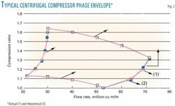
There are distinct limitations on the stability range of a centrifugal compressor. Limiting the minimum capacity of a given centrifugal compressor is a phenomenon called "surge," which normally occurs at about 50% of the design inlet capacity at design speed (Fig. 2).2 3
The upper limit of capacity is determined by the phenomenon of "stone wall," which occurs when the velocity of the gas approaches its sonic velocity some where in the compressor, usually at the impeller inlet.
Planning model: flow rates
The general principle consists of choosing among all the technically possible flow rates,1 8 those satisfying the demand at the end of the pipeline, with minimum energy consumption. This choice will be possible only if we exploit the compressible character of the gas and the possibility of using the pipeline (especially the last pipeleg ) as a line pack, the line pack playing the constraining role.
Equation 6 gives the objective function.
The constraints governing the model are shown in Equations 7, 8, 9, 10, and 11. Equation 8 expresses the limitation of operating times by the planning duration.
The problem set that way may be solved by a linear-programming procedure using a simplex algorithm.6
Executing this program must overcome two essential difficulties:
The very high number of operating flow rates technically realizable.
The definition and the calculation of line pack capacity.
Overcoming the first difficulty uses the following principle:
For a given flow rate, there is a single optimal configuration of compressor stations corresponding to a minimal fuel consumption value.3 A suitable discretization permits a return of the phase space to a reasonable dimension (less than about dozen flow rates, or variables).
Table 1 summarizes the results for various flow rates.
Ling pack
Because the pressure drop in natural gas transmission lines during off-peak periods is less than during peak-load periods, the average pressure along the line will be greater. The line thus serves an important secondary function, that of storage.
Weymouth defined the storage capacity of a natural gas pipeline as the difference between the gas contents of the pipeline under packed and unpacked conditions.
A pipeline is said to be "packed" when withdrawal from it is at a minimum and when, therefore, for a constant supply of gas, the discharge pressure is a maximum. A pipeline is "unpacked" when withdrawals are at maximum and pressure is at minimum for a constant supply of gas to the line.
With this definition of storage capacity and the Clinedinst equation,8 an expression can be derived that considers the variation in compressibility of the gas with pressure. The content of a natural gas pipeline under conditions of isothermal flow is then Equation 12.
Pipelines' storage capacities
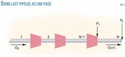
One of the methods for meeting the demand fluctuation at the end of a pipeline consists of using the last pipeleg as line pack. In this case, the working conditions of the last pipeleg are evidently different from those of the other pipelegs.
The (N–1) first pipelegs are characterized by a constant flow rate Qo, steady state corresponding to the average flow (Fig. 3). For the Nth pipeleg, the flow rate at the inlet and at the outlet may be different: Qo≠Q1.
When the demand is less than the steady-state flow rate, gas accumulates in the last pipeleg,9 which leads to an increase in the average pressure. In the opposite case (Q1>Qo), a complementary amount of gas is drawn from the storage and the average pressure decreases.
The main problem with using the last pipeleg as a line pack is to ensure that the distribution of pressure along the pipeline will not exceed the technical limits of pipe resistance and the maximum and minimum pressures at the beginning and at the end of the pipe.
It is evident that the flow in the last pipeleg is unsteady (dynamic). This type of flow is described by a system of partial differential equations of hyperbolic type.
The solution of this system can be obtained using two ways :
- Analytically, proceeding with linearization.
- Numerically, with a finite-differences scheme.4
Calculating the upstream and downstream pressures assumes a steady-state regime. In steady state, the mass flow rate is expressed by Equation 13. Assuming Equation 14 leads to Equations 15 and 16.
The average pressure is expressed by Equation 17. Dividing Equation 17 by Equation 13 yields Equation 18.
Knowing the average pressure allows the determination of e and, therefore, also P1 and P2.
Determining these is possible by two methods: graphic resolution and numerical resolution.
To calculate the average pressure, we use gas state equation, Equation 19. Or, the density of the gas is expressed by Equation 20.
If Equation 20 is substituted into Equation 19, the expression for the average pressure becomes Equation 21. The gas mass is calculated with Equation 22.
If Q1 is a function of time, discretizing yields Equation 23 and, therefore, the definition of the maximum line pack value.
As an example, the results of the proposed model to the 573 km, 40-in. GK1 Algerian gas pipeline which feeds natural gas from the Hassi R'mel fields to liquefaction units at Skikda.
A flow rate at the end of the pipe of 1.35 million cu m/hr and a planning period of 24 hr allow a gain of about 13,980 cu m/hr.
References
1. Ainouche, A., and Smati A., "Global Optimization of the Algerian gas pipeline network," 16th World Petroleum Congress, Calgary, June, 2000.
2. Ainouche, A., and Smati, A., "Optimization of LNG chain by stochastic dynamic programming model," 17th World Petroleum Congress, Calgary, Sept. 1-5, 2002.
3. Ainouche, A., Smati, A., and Younsi, K., "Optimisation des régimes d'exploitation d'un gazoduc par un modèle de programmation non linéaire," CIP 2001, June 9-11, 2001, Algeria.
4. Cheesman, A.P., "How to optimize gas pipeline design by computer." Oil & Gas Journal, 69 (No. 51) , Dec 20, 1964 (1971 a).
5. Furness, R.A., "Modern pipeline monitoring techniques," Pipes and Pipelines International, May 1985.
6. Gass, S.I., Linear Programming, 5th ed., McGraw-Hill, New York.
7. Handbook of Natural Gas Engineering, Gulf Publishing Co., Houston, 1980.
8. Smati, A., "A systemic approach in optimization of the Algerian crude oil network," Proceeding Intern. AMSE Conference, July 4-6, 1994, Vol. 3, Lyon, France.
9. Smati, A., and Ainouche, A., "Algorithmes adaptatifs d'optimisation d'un gazoduc," Proc. Conf méditerranéenne d'électronique et d'automatique MCEA 95, Grenoble, France.
The author
Abdelhakim Ainouche ([email protected]) is a hydrocarbon and gas processing senior engineer for Sonatrach, Algeria. He graduated from the National Algerian Institute of Hydrocarbon and Chemistry. He is a member of the Algerian gas industry association.
