Method calculates SIF for branch piping connections
A method has been developed for calculating the nominal wall thickness of matching pipe for certain sizes of branch connections and stress intensification factor (SIF) and for designing branch connections to withstand pressure and certain bending moments.
The method allows for a safe reduction in the cost of the entire piping system by more accurately calculating the stresses in the branch connections.
Branch connections are one of the most stressed parts of any piping system. In addition to internal pressure loading, bending moments can be applied in the branch connections of piping or pipeline system. These bending moments may be caused by thermal expansion or contraction, dead and live loads, movement of piping supports, and external forces.
American Society of Mechanical Engineers (ASME) B31 Codes for Pressure Piping provide a detailed engineering method for pressure design of branch connections. The method for bending moment design of branch connections, however, is not well defined.
According to the code, the bending stresses in the branch connections depend on the section modulus of the pipe and SIF, both of which are based on nominal wall thickness of matching pipe. The code does not define "matching pipe."
The actual adjoining pipe to which the branch is connected cannot be interpreted as the matching pipe in many cases because it is not required that adjoining pipe and branch connection have the same design pressure-temperature rating.
Method basis
The engineering method for pressure design of branch connections, provided by B31 Codes, rests on the principle that a pipe having a branch connection is weakened by the opening and that reinforcement is therefore required to sustain the pressure of the header pipe. The minimum amount of reinforcement derives from the condition that the required area of reinforcement exceed what is required for a straight pipe, i.e., the wall thickness of the run and branch pipe, and that the area of metal provided by welds and attached reinforcement shall be equal to the area of opening.
This approach to the design of branch connections ensures satisfactory performance of the branch connection to internal pressure only.
The code states that special consideration be given to the design of a branch connection to withstand external forces and movements that impose bending stresses (flexibility stresses analysis) on the header and branch. Flexibility stress analysis is based on bending stress that is calculated with consideration of SIF.
ASME B31 Codes provide equations for calculating in-plane and out-plane SIFs for some types of branch connections. These equations are based on the nominal wall thickness of the matching pipe. Therefore, a definition of matching pipe is required, along with a method for determining the nominal wall thickness of matching pipe.
The definition of matching pipe, proposed here, follows from the principle used in pressure design of branch connections: The matching pipe of the branch connection is the calculated straight seamless pipe that has the same pressure-temperature rating as the branch connection.
This general definition allows development of the method for determining nominal wall thickness of matching pipe and SIF.
Designing connections
The approach used in piping and pipeline design of branch connections may be divided into three categories.
1. Certain branch connections have been manufactured according to referenced standards in the B31.3 Code and have established pressure-temperature rates. For these branch connections, the nominal wall thickness of matching pipe should be calculated in accordance with applicable ASME B31 Code as wall thickness of straight seamless pipe due to pressure.
For this calculation, the outside diameter of the run and the material that is equivalent to that of the fitting should be used. In most cases the pressure rating of adjacent (not matching) pipe or the grade of material is more than the pressure rating and grade of the branch connection material.
2. Certain branch connections have established size and grade of material. In these cases, the nominal wall thickness of matching pipe should be determined based on calculating maximum allowable design pressure for the branch connection.
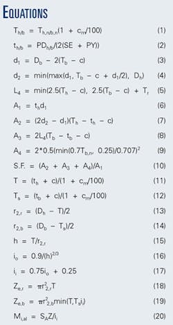
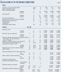
The procedure for calculating the nominal wall thickness of matching pipe and SIF is given Table 1. The input data for this example are the same data used in Sample 1 in Appendix H of ASME B31.3-2002. The equations used in the calculation appear in the accompanying equations box. The equations, nomenclature, and definition are according to B31.3 Code. An Excel Spreadsheet was used to generate Table 1.
The calculation in the first column of the table represents exactly the problem given in Sample 1 of Appendix H of B31.3-2002 and answers the question if additional reinforcement is necessary by calculating the safety factor. The safety factor is calculated as a ratio of total reinforcement area to the opening area per Equation 10. The safety factor value >1 shows that additional reinforcement is not required. The code sample, however, does not determine pressure rating and the wall thickness of matching pipe. The value of actual pressure in the input data does not represent the pressure rating of this branch connection.
The second column in Table 1 represents the calculation of matching pipe nominal wall thickness and the SIF for the same size of branch as in Column 1. The definition of matching pipe cited previously requires determining the pressure-temperature rating. To determine the pressure rating, the actual value of pressure in the first row has been changed to the value that produces a safety factor = 1. This means that this pressure is the allowable and represents the pressure rating of the branch.
For this branch connection, the allowable pressure of 377 psig is 25% more than the actual pressure.
Equation 11 calculates the nominal effective wall thickness of matching pipe based on pipe-required thickness for the allowable pressure. The Excel spreadsheet format allows automatic calculation of the pipe-required thickness for allowable pressure per Equation 2. With the nominal effective wall thickness of the matching pipe, the stress intensification factors and effective section modulus can be determined per Equations 16-19, in accordance with B31.3.
The effective section modulus allows for calculating the allowable bending moment based on allowable flexibility stress range per Equation 20. The last rows on the table consist of the allowable in-plane bending moments assuming the simplification that bending take place only in-plane. It should be noted that the more correct calculation of matching pipe thickness based on allowable pressure rating of the branch connection increases allowable bending moment about 19% for this example.
3. Occasionally situations occur in which the actual bending moment in branch connections of the piping or pipeline system is higher than the allowable bending moment for branch connection designed to withstand only the internal pressure.
Different methods can reduce bending moments. In some cases, changing the size or the grade of material of branch connections may be more cost-effective than changing the piping configuration and (or) adding additional supports.
The third column in Table 1 represents the result of calculating a branch connection with increasing wall thickness of the header and branch to withstand a higher bending moment. In this example, the change of wall thickness from standard to extra strength allows an increase in the allowable bending moment of about 82%.
This proposed practical engineering method, based on B31.3 requirements, of determining nominal wall thickness of matching pipe for certain branch connections or to design branch connections to withstand certain bending moments can provide a safe way to reduce the cost of a piping system.
Although the proposed method uses ASME B31.3 equations, the method may be used for piping and pipeline systems designed per any B31 Codes for Pressure Piping with some modifications that reflect a specific requirement of the certain B 31 Code.
The authors
Alexander Aynbinder ([email protected]) is a senior principal engineer at Gulf Interstate Engineering Co., Houston. Previously, he was in the pipeline engineering department of Fluor Daniel Co. Before emigrating to the US in 1990, Aynbinder was a lead research scientist in the Russian State Research Institute for Pipeline Construction (VNIIST). He is a graduate of the Moscow Civil Engineering Institute and holds a PhD in civil engineering from the Central Research Institute of Civil Structures (CNIISK), Moscow.
Joseph A. Bohinsky is manager of quality assurance for Gulf Interstate Engineering Co. and previously held the position of manager of engineering. He has more than 30 years' experience in oil and gas engineering and pipeline engineering. Bohinsky holds BS and MS degrees in civil engineering and an MBA and maintains professional engineering registrations in 40 US states and a province of Canada.


