Pipe diameter does not affect black powder distribution, erosion
Ehab Elsaadawy
Abdelmounam Sherik
Saudi Aramco
Dhahran
Pipe diameter seems to have no influence on black powder particles' velocity distribution in natural gas transmission pipelines operating at 10 m/sec and 20 m/sec, and there will be little, if any, particle-size segregation. Filter systems installed on such pipelines should be sized to collect the entire particle-size spectrum.
A pipeline bend with longer radius of curvature (e.g., 3.0) will have more uniformly distributed erosion over the outer wall of the bend, making it a better candidate for applications in severe erosive service environments, such as black powder contamination. But black powder erosion even in bends of smaller ratios is negligible.
Background
Black powder particles in sales gas pipelines are hard and jagged, making them potentially erosive to pipeline bends and control valves. A computational fluid dynamics study predicted the flow of black powder particles in transmission gas pipelines and the erosion rate in pipeline bends. This article examines the flow of black powder particles, under scraping conditions, in gas pipelines with varying diameters and gas flow rates and presents results. It also predicts erosion rates of pipeline bends with different radius of curvature to pipe diameter ratios and flow rates.
Under the conditions studied, particles' velocity profiles are insensitive to pipe diameter and the larger pipeline bend exhibited a more uniform erosion rate distribution than the smaller one. Erosion rates in both cases, however, were negligible and should not affect the operational life of the bends.
Black powder generated in Saudi Aramco's sales gas transmission pipelines consists mostly of magnetite (Fe3O4) particles which are hard (53 Rockwell C) and sharp edged. This combination of high hardness and sharp shape makes pipeline bends and tees potentially prone to erosion failures due to black powder particles' impingement.1-5
Previous research has focused on solid particle (other than black powder, such as sand, etc.) erosion of pipelines and pipeline bends. Few studies, however, have addressed the flow of black powder in pipelines6 7 and none has addressed erosion of pipelines bends due to black powder impingement.
Previous black powder studies used the semiempirical approach to calculate the required fluid velocity to entrain and carry away black powder particulates in liquid and gas pipelines,6 7 concluding that the velocity required to move black powder particles in gas pipelines is independent of particle size and ranges from 10.4 fps to 13.6 fps for 8-in. OD and 30-in. OD pipelines, respectively. The velocity required in water transport pipelines, by contrast, depends on particle size, up to about 5.0 mil (0.127 mm) after which it depends only on pipe diameter.
Mathematical model
In situ isokinetic sampling of sales gas containing black powder particles showed the black powder volumetric loading ratio as typically 3.2 x 10⁻⁷, allowing the flow to be dealt with as a dilute gas-solid multiphase flow. The Eulerian approach, therefore, modeled the continuous phase, while the dispersed phase, including the particles, was modeled using the Lagrangian approach. The Lagrangian approach calculates the trajectory of several individual solid particles through the flow field. The motion of the tracked particles helps describe the average behavior of the dispersed phase.
A commercial CFD software package allowed building and solving the mathematical model.8 The continuous gas phase solved the Reynolds Averaged Navier-Stokes (RANS) equations for steady, incompressible, and isothermal flow, specifically the continuity and the momentum equations. Solving a Finnie-based erosion model along with the RANS allowed prediction of erosion rates.
Model assumptions were as follows:
• Only the influence of turbulent fluid fluctuations on particle motion was considered with the stochastic tracking discrete random walk model. The particle-particle interactions are neglected and any change of the flow turbulence caused by the particles is not accounted for (i.e., one-way coupling).
• Noninteracting and nonfragmenting particles are considered.
• Geometry modifications due to material removal by erosion were neglected, making the computational model geometry during simulation invariable.
Integrating the force balance on the particle determines trajectory. Force balance equates the particle inertia with the forces acting on the particle, Newton's second law (Equation 1).
The forces acting on a particle can be drag, buoyancy (gravitational settling), pressure gradient, and added mass, Brownian diffusion (motion), Saffman lift, and Basset, and rotating reference frame force.
For small particles with a density ratio much greater than 1, only the drag force and the gravitational settling force will affect the trajectory of the particle, with other forces negligibly small.
Equation 2 shows the reduced form of the equation of motion along a particle trajectory. Although Equation 2 is linear, the fluid velocity along the particle trajectory must be known in order to solve it. Velocity depends on the particle path itself, making the general solution in even a simple turbulent flow unusable.
Particle trajectory calculation includes logging of such particle-wall interaction information as impact speed, impact angle, impact location, and impact intensity. Applying this information to the appropriate erosion equation allows calculation of erosion. The model uses methods based on the Finnie model to calculate erosion rate (Equation 3).
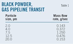
This article examines five simultaneous particle injections, representing actual field conditions given in Table 1, released from the flow inlets. The particles had a velocity and uniform distribution equal to that of the gas. The stochastic discrete random walk (DRW) model accounted for turbulence's effect on particle trajectories.
Geometry, flow
The gas phase used in this article is a typical Saudi Aramco sales gas at operating conditions, with a mass density, ρ, of 61.8 kg/cu m and a dynamic viscosity, µ, of 1.33 × 10⁻⁵ Pa·sec. The gas flow rates used resulted in bulk gas velocities, vb, of 10 and 20 m/sec. The black powder (magnetite) has a mass density, ρp, of 5,150 kg/cu m and was released at a rate of 2.4 x 10⁻³ kg/sec into the stream. Table 1 summarizes particles sizes, dp, and corresponding mass flow rates. These particle conditions typically follow scarping conditions. Field measurements determined that the black powder particles are smaller in size but with much higher loading after scarping, increasing their erosive force and making them the focus of this article.
This article considered pipeline diameters typical of sales gas pipeline systems. Flow rates considered ranged from low to high demand rates of the sales gas system. Table 2 summarizes pipe sizes, flow rates, and the corresponding Reynolds numbers, ReD = ρvbD/µ, and particle Stokes numbers, Stp = ρpvbd2p/18µD.
The pipeline bend under study is a standard 90° bend with 36-in. OD. The ratios studied of the bend radius of curvature, R, to pipeline diameter are 1.5 and 3.0. The bend has a 20-ft inlet horizontal pipe an 80-in. vertical outlet pipe. The bulk gas velocities, υb, studied are 5, 10, and 20 m/sec. The pipeline bend consists of A53-B carbon steel.
Validation
The published experimental data of Yang and Kuan9 10 using a dilute gas-solid flow through a curved 90° duct bend validated the mathematical model.
Results
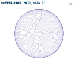
Fig. 1 shows a sample mesh of the 48-in. OD pipe used in computations. The mesh, inflated in the vicinity of the wall, captured the high-velocity gradients in that region. Similar meshes did the same for the rest of the pipes.
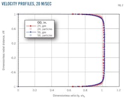
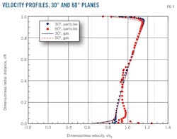
Fig. 2 shows the normalized particles' velocity profiles and gas velocity profiles at different pipe sizes (24 and 56-in. OD). At a gas velocity of 20 m/sec, black powder particles will suspend in the gas stream and flow downstream at the same velocity as the gas. This flow will continue unless obstructed by a bend or a valve where sudden changes in direction may promote particle segregation. A 10-m/sec gas velocity produced similar results.
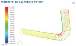
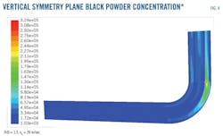
Fig. 3 presents velocity vectors along the vertical symmetry plane for pipeline bend (radius of curvature/diameter) R/D = 1.5. The left-to-right flow of the bend has a gas bulk velocity, vb, of 20 m/sec. The velocity contours show flow accelerating close to the inner wall as it enters the pipeline bend due to the favorable pressure gradient at that part of the wall, while it decelerates at the outer wall due to the adverse pressure gradient. This behavior starts to reverse after the bend midpoint, i.e., at a 45° plane. This centrifugal effect causes the particles to partly concentrate closer to the outer wall (Fig. 4).
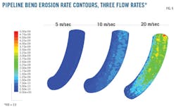
Fig. 5 compares gas and particle velocity profiles at two cross sections of the pipeline bend (30° and 60° from the inlet plane). Particles follow the gas with negligible slip except at the 60° plane where they deviate close to the outer wall of the bend. The adverse pressure gradient causes gas to decelerate at this wall, while particles lag in response and continue to move with higher velocities. The inner wall of the bend encounters a higher velocity stream, but the outer wall of the bend has a higher erosion rate due to the impact angles of particles. Fig. 6 compares the contours of bend erosion with R/D = 3.0 at different bulk gas velocities (5, 10, and 20 m/sec). The higher the bulk gas velocity, the higher the erosion rate. The erosion, however, is spreading over a wide area of the bend wall and has a very small value.
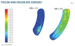
Fig. 7 shows the erosion contours predicted for a pipeline bend of R/D = 1.5 as concentrated in a smaller region, where maximum erosion takes place at the midpoint (along the symmetry plane) of the bend, the location where velocity profiles start reverse behavior. The maximum erosion value is higher than that of the longer radius of curvature bend, R/D = 3.0, suggesting that using a longer radius of curvature pipeline bend distributes the erosion rates more uniformly over the outer wall area of the bend.
Table 3 summarizes maximum erosion rates due to black powder. In an elbow of A-53B carbon steel alloy and R/D = 1.5 at a maximum bulk gas velocity, vb, of 20 m/sec, the loss of material thickness due to erosion is approximately 71.2 μm/year (7.12 mm/100 years).
Acknowledgments
The authors extend their appreciation to Dr. Benny Kuan of Commonwealth Scientific and Industrial Research Organization (CSIRO), Australia, for providing the experimental data used in validating the mathematical model used in the current study. The authors acknowledge Saudi Arabian Oil Co. (Saudi Aramco) for its support and granting permission to present and publish this work.
References
1. Sherik, A.M., "Black Powder—1: Study examines sources, makeup in dry gas systems," Oil & Gas Journal, Vol. 106, No. 30, Aug. 11, 2008.
2. Sherik, A.M., "Black Powder—Conclusion: Management requires multiple approaches," Oil & Gas Journal, Vol. 106, No. 31, Aug. 18, 2008.
3. Tsochatzidis, N.A., "Study addresses black powder's effects on metering equipment," Oil & Gas Journal, Vol. 106, No. 12, Mar. 31, 2008.
4. Tsochatzidis, N.A., and Maroulis, K.E., "Methods help remove black powder from gas pipelines," Oil & Gas Journal, Vol. 105, No. 10, Mar. 11, 2007.
5. Baldwin, R.M., "Here Are Procedures for Handling Persistent Black-Powder Contamination," Oil & Gas Journal, Vol. 96, No. 43, Oct. 26, 1998.
6. Smart, J., "Determining the velocity required to keep solids moving in liquid pipelines," Pipeline Pigging and Integrity Management Conference, Houston, Feb. 14-15, 2007.
7. Smart, J., and Winters, R., "Black powder migration in gas pipelines and associated problems," Pipeline Pigging and Integrity Management Conference, Houston, Feb. 13-14, 2008.
8. ANSYS Fluent 12 User's Manual, Ch. 22, ANSYS Inc., Lebanon, New Hampshire, 2009.
9. Kuan, B., Yang, W., and Solnordal, C., "CFD simulation and experimental validation of dilute particulate turbulent flows in a 90° duct bend," Third International Conference on CFD in the Minerals and Process Industries, CSIRO, pp. 531-536, Melbourne, Dec. 10-12, 2003.
10. Kuan, B., "CFD simulation of dilute gas-solid two-phase flow with different solid size distributions in a curved 90° duct bend," Third International Conference on CFD in the Minerals and Process Industries, pp. C744-C763, Melbourne, Dec. 10-12, 2003.
The authors
More Oil & Gas Journal Current Issue Articles
More Oil & Gas Journal Archives Issue Articles
View Oil and Gas Articles on PennEnergy.com


