Programmed route markers increase efficiency, safety
New buried identification marker technology offers potential improvements in oil and gas pipeline-maintenance efficiency and reduction of the likelihood of accidental damage and associated safety hazards.
Electronic marking, locating, and identifying of systems used by telephone companies, power companies, water and sewer utilities, and cable companies can also protect underground gas and oil pipelines in urban and rural settings by marking road crossings and important buried features such as valves, stubs, and turn points.
The US natural gas infrastructure includes about 1.4 million miles of underground pipeline. US Office of Pipeline Safety records show that during the first 6 months of 2006 there were 16 incidents of third-party excavation damage to natural gas distribution pipelines at a cost of $1.22 million, one related death, and two serious injuries.
Four incidents of third-party excavation damage to transmission pipelines during this same 6-month period totaled $173,000 in damages. During all of 2005, there were 19 such natural gas transmission line damage accidents (costing $2.48 million) and 67 distribution line incidents (with $8.5 million in damages).1
Unintended contact during excavation or trenching commonly causes gas-pipeline accidents, which occur when construction companies and grading crews perform work without proper one-call notification or fail to follow common-sense digging practices.
Locating, marking
Traditional utility-locating equipment injects an RF signal into a conductive object in the ground, such as a pipe or cable, to indicate the presence and path of a buried utility. This technology only approximates utility depth and location and works only with metallic objects. Passive markers buried adjacent to utility components respond to signals from a locator device and can be pinpointed precisely as to location and subsurface depth.
Electronic underground markers require no external power source, and are not disturbed by surface grading or construction. Their usefulness, however, is limited as they indicate simply that some utility is buried at the marked point. The effective message of an electronic marker is: “dig here to learn more.”
A new buried identification marker system incorporates preprogrammed marker identification, making it possible to locate and identify quickly the depth and exact properties of the marked object without excavation.
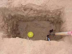
The electronic system uses 4-in. diameter plastic balls that are located and read with hand-held locators by means of utility-specific radio-frequency signals. Individual colors and interrogation frequencies distinguish between gas, waste water, potable water, CATV, telephone, electrical power, and general purpose underground marking applications. The ID markers require no external or internal source of power and are energized solely by electromagnetic energy received from the interrogating marker locator.
ID markers use application-specific integrated circuit (ASIC) chips to store static information, and each marker has a unique factory-assigned serial number for association with a specific location and for printing on as-built buried-facility drawings. The markers also have a memory capacity for storing custom labels and descriptions. The user can write these data to the chip anytime before placement in the ground.
Ball markers are programmed, located, and read by means of a multifunction locator. This unit uses an RS232 communications port to interface with an external computer to download and upload marker information for record management and mapping.
Unlike roadside signs or surface markers, buried ID markers are not subject to random damage. They resist moisture and varying temperatures, require no electrical power, and are designed to last for the life of the buried facility. The internal antenna component is self-leveling and automatically orients in a horizontal position for maximum signal strength when the ball marker is placed in the ground.
As ID markers are placed, removing an adhesive label with a unique serial number and associated bar code from the ball and placing it on a field map provides an initial record of the marked location. The same details are temporarily stored in the marker locator device for downloading to a computer. Stored data update the utility mapping and infrastructure database.
An accessory device for the marker locator measures and records global positioning satellite (GPS) coordinates for each marked location. This GPS information is also stored in the unit during each shift for downloading in support of GIS mapping.
Application example
BP Gas has adopted ID markers for protection of rural road pipeline crossings as part of its San Juan operations center in northwest New Mexico. This center oversees 5,500 sq miles in three counties, which include several thousand natural gas wells and nearly 500 rural road pipeline crossings. Because a substantial portion of BP gas lines in this operating region is made of fiberglass, they cannot be located with traditional equipment.
Crews typically grade the gravel or dirt roads in the area at least twice a year. Because grade levels may change depending on soil conditions, rain, winter runoff, and grading activity, road crews need accurate and dependable information on the depth of every pipeline before they can safely grade a road. BP’s ground-disturbance policy mandates that no mechanical equipment be permitted within 24 in. of buried facilities to safeguard against injury, shield the underground infrastructure from damage, and protect the environment.
After a preliminary field test of ID markers, BP instituted a program of marking every road crossing in the region, generally using three programmed ball markers per crossing: one over the pipe on each side of the road and one in the center of the road.
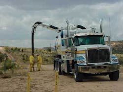
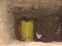
The marking program performed vacuum excavation of pipelines at each road crossing, followed by backfilling to a measured depth (typically 3-4 ft below the surface). The on site team would then program an identification marker ball with the measured distance from the pipe to the electronic marker and place it in the partially backfilled hole.
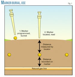
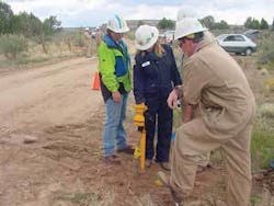
The locator accurately measures the distance from the surface to the marker (which varies with grading) and reads the fixed marker-to-pipe distance recorded on the marker, making calculation of the total surface-to-pipe distance for each marker easy (Figs. 1-5).
Details programmed on each marker include company name, measured depth from marker to pipeline, and pipe size and type.
County road-grading contractors in this New Mexico region can now access maps that show the location and depth of each buried gas line crossing, each of which is also registered with the New Mexico one-call system. BP will periodically monitor gas line depths in the region, using marker locaters to find and read the buried marker balls and updating published records appropriately.
High-risk areas where erosion is likely to lead to grade shifts or where soil conditions could cause line movement are monitored most closely.
BP is now installing ID markers at rural locations in Colorado. This technology may eventually be used in other BP operating areas having numerous rural road crossings, including Wyoming, Kansas, Oklahoma, Texas, and Louisiana. The company anticipates that ID marking will result in measurable cost savings because it eliminates the need to periodically pothole each road crossing to maintain ongoing accuracy of pipe depth records.
Reference
- http://ops.dot.gov/stats/LQ_SUM.HTM.
The author
Corey M. Willson (cmwillson @3M.com) is a product manager for 3M Track & Trace Solutions. He earned a BSME from the University of Texas at Austin, and has 17 years’ experience in the manufacturing and application of underground marking and remote locating and test technologies in utility applications.
