X80 pipe-welding technique yields reliability, cost advantages
Ricardo Fernández
Centro Nacional de Investigaciones Metalúrgicas
Madrid
Angela Lazaro
Soluciones Industriales y Soldadura|
Santa Olalla, Spain
Carmen Peña Fernández
Centro Nacional de Investigaciones Metalúrgicas
Madrid
Juan Manuel López Escobar
Carlos Perez Arnaez
Enagás Transporte
Madrid
The combination of gas-shielded flux-cored arc welding (FCAW-G) and shielded-metal arc welding (SMAW) or gas-metal arc welding (GMAW) in the root pass generate reliable girth welds in X80-grade pipelines and present clear practical advantages—weld reliability in all positions and the productivity offered by a semiautomatic-mechanized process— without significantly higher costs. Flexibility in selection of joint and bevel preparation is another important aspect. These characteristics make it very attractive for field pipeline girth welding.
Background
Steels available to the pipeline industry fall into two main groups. Steels up to Grade X70 are considered conventional. Most of the pipelines constructed around the world belong in this group. The tendency, however, is changing towards higher grades. The higher-grade steels, such as X80, were developed during the 1980s and show improved mechanical resistance. The use of higher grades also reduces the logistics costs and the extent of welding. The material grade used in a pipeline represents about 40% of its total cost.
In recent years, even higher grades such as X100 and X120 have been considered for construction of very large pipelines. But, in practice their use has been very limited. Nonetheless, it is recognized that efforts should be made to convince gas network operators to use these high-grade steels, X100 or X120, despite their not being included in current gas industry practice. Qualification and fabrication of these pipelines, however, impose large problems for the industry despite the strong commitment to introduce these new materials due to their outstanding properties.
The properties of high-grade steels are mainly related to their method of fabrication. Thermomechanical and accelerated cooling treatment (TTMC) is currently used to obtain higher grades of steel with improved microstructures compared with conventional grades. X80 material in particular typically shows a fine-grain bainitic microstructure that provides higher strength than X60 or X70 while having sufficient toughness to meet international standards. X80, however, is more prone to provoke weld defects than ferritic matrix materials.
SMAW and GMAW are widely used for field welding in the pipeline industry. All common processes—GMAW, submerged arc welding (SAW), and flux-cored arc welding (FCAW)—have been studied as potential candidates for the fabrication of pipelines using higher-grade steels. Moreover, a combination of techniques such as GMAW and SMAW or GMAW and gas-shielded FCAW (FCAW-G) have been considered for the construction of large pipelines. Very innovative welding processes such as hybrid laser arc welding and friction stir welding also have been studied (though mainly for the manufacturing of the pipes themselves), as well as high productivity SAW techniques.
Criteria and verifications established by international standards such as API 1104, ASME IX, and EN-12732 are commonly used to qualify the welding of a gas pipeline. There are three fundamental properties to bear in mind when considering the use of a high-grade material, such as X80, for construction of gas transport infrastructure: mechanical resistance, toughness, and weldability.
The strength of an X80 material is superior to the more widely used X70 grade. But this improvement in strength must compensate for potentially poorer weldability and deformability which could result in a structure more prone to failures. The main criteria used to evaluate the quality of girth welds are summarized in international standards.
In this article, the weldability of X80 girth welds produced with FCAW-G combined with other processes (SMAW and GMAW) are compared with those typically used in the pipeline industry, such as SMAW and GMAW. The welds have been tested in accordance with API 1104 and EN-12732 standards and included consideration of ASME Section IX code. The quality of the girth welds was evaluated through correlating the microstructure-mechanical properties of welded joints.
The main goal is to verify if welding processes combined with FCAW-G can maintain sufficient mechanical characteristics as to prevent pipeline failures, while at the same time being practical and cost effective for use with X80-grade pipe. Welding parameters and joint preparation, including preheating necessary to achieve the weld’s expected mechanical characteristics, are considered.
Materials, methods
The study underlying this article was carried out on a 406.4-mm (16-in.) OD and 14.38-mm WT API 5L X80 PSL2 (X80 hereafter) tube manufactured using electric resistance welding (ERW) high-frequency induction (HFI). Welding procedures like those commonly used in the construction of gas pipelines were selected. Testing of the welded specimens measured the mechanical characteristics obtained with each process, and the weldability of the material. These tests ultimately provided data and firsthand information allowing selection of the most appropriate processes in the construction of a future infrastructure.
The metallographic study of welds used transverse sections of 80-mm machined prismatic samples centered in the weld seam. The specimens were prepared by conventional grinding and polishing and etched using 2% Nital reagent to show the different welding zones and their microstructures. The grain size and crystallographic orientation were determined by optical microscopy and electron backscatter diffraction (EBSD), respectively. An Oxford instrument EBSD system attached to a Jeol JSM 6500F field emission-scanning electron microscope were used to characterize the crystallographic orientation in the weld material and heat-affected zones (HAZ). The increment used for EBSD maps was 0.3 µm.
Chemical analysis
Combustion in an induction furnace and detection of carbon (C) and sulfur (S) by infrared absorption determined C and S content. Spark optical emission spectroscopy (GDOES) determined the rest of the elements.
Table 1 shows analysis results. The values correspond to the average value of three independent determinations for the tested sample. These results correspond to the chemical composition specifications included in the API 5L-ISO 3183 for a steel grade L555Q or X80M, with reference to the elements analyzed.
Mechanical characterization
Prismatic samples of 55-mm length centered at the HFI bond line of the line pipe and the girth welds were machined in the transverse section. The samples were grinded, polished, and etched with Nital 2%, in a conventional metallographic preparation until a mirror finish was obtained showing the different microstructural areas of the weld. Hardness tests were carried out with a Vickers hardness tester at room temperature and with 10 kg of applied load. Two rows of indentations were made on the specimen corresponding to the inner and outer areas of the pipe wall.
The tensile tests of the pipe material and transversal test to the girth weld were carried out using standardized round bar specimens. The strain rate during the test was 5 × 10⁻⁴ s-1.
Cylindrical samples (6.2-mm diameter, 26-mm calibrated length), with all weld metal specimens mechanized longitudinally to the weld bead, allowed mechanical characterization of the studied welds’ metals.
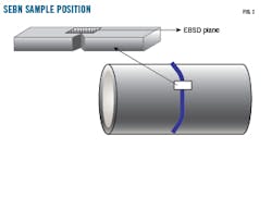
Charpy and crack-tip opening displacement (CTOD) tests were carried out in single-edge bend notch (SEBN) samples notched in the HAZ and weld metal and machined according to the sketch shown in Fig. 1. The samples’ dimensions were 10 × 7.5 sq mm section, 55 mm long. A 2-mm deep V-groove was machined in the Charpy specimens. The CTOD deep groove was 0.1 mm wide, with a 60° radius. Each specimen was chemically etched with metallographic reagent (Nital 2%) to precisely locate the notch in the required testing position. The testing temperature was -18 ° C. A Colora Ultra-Kriostat KT905 Cryostat cooled the samples.
The Charpy tests used a Charpy impact flexure pendulum with a full scale of 300 J. The CTOD samples were pre-cracked in force control mode according to ASTM-1820 and ISO 12135 standards. The CTOD tests were carried out in a 100-kilonewton (kN) Microtest universal testing machine under force control mode at 20 newtons/sec until either maximum load or crack unstable propagation was reached.
Welding processes, procedures
Manual welding processes, which involve less investment in equipment and logistics and have more construction companies available and prepared to execute the jobs, are still widely used. The first tests, therefore, were conducted on welds using completely SMAW procedure. Due to characteristics of the steel, a root pass using a cellulosic-type electrode followed by fill and capping passes with a low-hydrogen electrode were selected.
During the 80s, following the general trends of other industries, semiautomatic welding processes began to be used in pipeline construction. The lack of highly skilled welders together with the improvement of weld productivity guided contractors to employ these processes, which are still used for gas pipelines when factors such as distance, difficulty, or diameter, do not justify the use of mechanized processes. A procedure using the manual SMAW process for the root pass and semiautomatic FCAW-G process for the remaining passes, therefore, was also included for comparison.
Mechanized processes were more widely used towards the end of the 90s, and are the preferred choice for large projects, even those involving smaller pipelines. Considering this, three fully-automatic procedures combining different welding processes were also developed to compare with different aspects of this article’s research.
As a summary, two manual and three mechanized processes were designed to study the effects of filler metal, welding process, and technique on the microstructural and mechanical characteristics of the joints.
- SMAW. The SMAW technique requires a constant-current power source capable of maintaining a stable arc, and a highly skilled welder. However, the investment on the welding equipment is quite affordable. Moreover, there is higher margin for bevel preparation allowance and joint configuration of the pipes since the welder can perform quality welds on imperfect joint preparations. The main limitation of the process is that sound welds are highly dependent on the welder’s skill level. In addition, filling the joint requires a greater number of passes, meaning the process is slower compared with the mechanized processes.
- SMAW + FCAW-G. This procedure combines the flexibility of the bevel and joint preparation in the root pass, without the need for backing, and the productivity advantages of the semiautomatic process. The number of passes required to complete the joint are significantly less than with SMAW. The investment in the constant-voltage welding sources required for this is slightly higher than SMAW. But the additional investment cost is compensated for by greater productivity.
- GMAW-P. This is the process most widely used by companies having fully-automated solutions for welding pipelines. The investment in GMAW-P welding equipment as well as the programmers needed to provide continuous control and adjustment of the welding parameters throughout the all-position circumferential joint is much higher than the investment required for the other processes. Moreover, perfect and repetitive joint preparation is an absolute requirement in obtaining sound welds, requiring further investment in beveling machines and powerful clamps.
The use of a copper backing is under discussion because of the risk of weld cracking due to copper-grain boundary segregations, even after the pipe has been in service. Companies are working on improving welding parameters and joint configurations to avoid this risk. In addition, welding equipment manufacturers are improving features to perform sound root passes without the need for copper backing.
Special pulsed modes together with the programming capability of the welding machine also allow for improved arc control at each sector of the circular weld. The weld puddle, however, is very difficult to control and can result in poor fusion of the weldment to the base metal and between subsequent weld passes. This phenomenon is commonly known as incomplete fusion and is difficult to detect by nondestructive examination. A very strict monitoring of the welding variables is necessary, therefore, which in turn requires implementing production quality control methods, and normally involves destructive examination of the welds. If a failure is detected, the risk exists that all the welds produced that day may require repairs.
- GMAW-P+FCAW-G. The speed of construction of a gas pipeline is very dependent on the speed at which the contractors can execute the first (root) pass. For this reason, much effort has been devoted to accelerating the rate at which root passes can be completed.
In the GMAW-P+FCAW-G process the risk of copper contamination during the GMAW root pass must be controlled. This combination, however, combines the benefits of the fully automated root pass with the higher reliability of FCAW-G (FCAW-S also sometimes is used) in all positions.
A process developed to weld in all positions eliminates the need for advanced welding equipment and sophisticated programmers for continuous arc control. The investment required for FCAW is significantly lower than that for fully automated processes.
GMAW-STT + FCAW-G. GMAW-surface tension transfer (STT) and similar processes can produce quality open-root weld passes, eliminating the need for copper backing. They are based on waveform control of pulsed-current welding machines. Each machine manufacturer has developed its own patented waveform control. Since each machine controls the arc in a particular way, the newer editions of international welding codes (API, ASME, EN) consider the specific model welding machine used as an “essential variable” during the qualification of the welding procedure to be used during construction.
GMAW-STT can be used with either semiautomatic or fully mechanized techniques. The semiautomatic technique produces sound welds on imperfect joint preparations, although requiring a skilled welder. The mechanized technique requires an investment in the automatic welding equipment and the joint-preparation equipment (beveling, clamps) used for each joint type, but is less dependent on the skill of the operator.
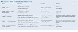
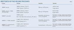
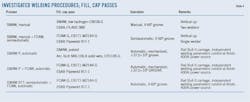
Tables 2-4 summarize the descriptions of the manual, semiautomatic, and mechanized welding procedures used in this article. A preheating of 100° C. and maximum inter-pass temperature of 250º C. were used for all welds. In the SMAW process using a high hydrogen-content filler metal (cellulosic electrodes), a dehydrogenation or soaking treatment at 100º C. was performed.
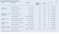
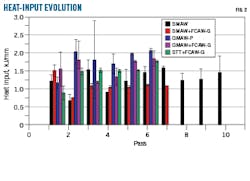
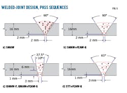
Table 5 summarizes the filler metal mechanical properties using actual values. The heat inputs for all the weld passes investigated are summarized in Fig. 2. The joint configurations for the studied welds are summarized in Fig. 3.
Results
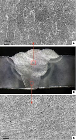
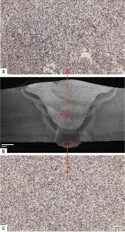
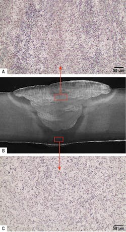
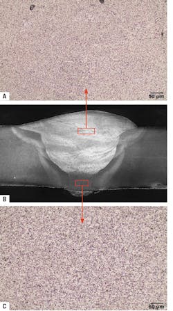
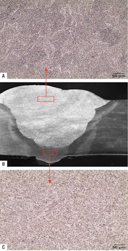
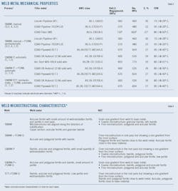
Figs. 4-8 summarize the studied welds’ macrographs. Table 6 does the same for microstructures obtained in the manual and mechanized welds. Microstructure in the weld metal contained acicular and polygonal ferrite with low bainite content.
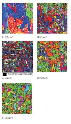
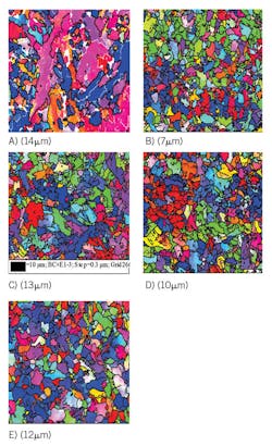
Microstructure aligned with the direction of solidification. In general, a coarser microstructure exists in fill passes. Microstructure in HAZ is highly dependent on the welding technique and weld material used. The grain size of the welds is shown in Figs. 9-10. Mean grain size is around 2 µm for all welds. But grains as large as 10 µm can be found in SMAW welds.
Large differences in effective grain size and orientation are present in EBSDs of the weld deposit materials studied. In manual SMAW welding a large grain size has no preferential crystallographic direction, which should produce good mechanical properties. Direction is measured by (hkl), which denotes the family of planes orthogonal to a given direction. In a cubic system, as iron, a crystallografic direction is described by {h+k+l}b, where b is the reciprocal lattice basic distance.
In the case of SMAW+FCAW-G welding (Fig. 9a), a considerably smaller effective grain size than SMAW is observed, with a significant orientation gradient. In the upper area of the map (Fig. 9b) grains (220 hkl) are dominant. While in the lower area, grains (200 hkl) and (111 hkl) are most observed. This texture gradient diminishes the mechanical properties of SMAW+FCAW-G welding.
Mechanized welding displays a smaller effective grain size, particularly in the case of GMAW-P welding, in which hardly any grains are observed oriented in the direction of cleavage (220 hkl) (Fig. 9c). In the other mechanized welds the effective grain size is between that of manual welds, but with a greater presence of grains oriented in the direction of cleavage in the STT+FCAW-G weld (Fig. 9e).
Mechanical properties
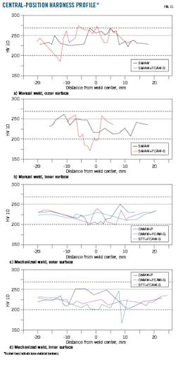
The maximum hardness increment is around 100 hardness value (HV) for the SMAW+FCAW-G process, accounting for the different welding consumables used in the root and cap passes. In the SMAW weld, again using different root and cap welding consumables, the hardness increment is roughly 50 HV.
In mechanized welds the hardness differences are much smaller. In the GMAW-P and GMAW-P+FCAW-G processes in particular, the inner region is harder than the outer region despite the reheating associated with the multi-pass welding. This can be explained by the combination of J-joint configuration and a low number of weld passes. This combination reduces the grain refinement associated with inter-pass heat treatment and the promotion of acicular grain shape from the external surface to the weld center (Figs. 6b and 7b).
The Rm obtained from the tensile tests in Table 7 are very similar for all welds, but lower than those of their correspondent welding consumables, with the exception of the SMAW weld (Table 5). Maximum resistance of the SMAW and the SMAW+FCAW-G processes are very similar, and even slightly higher than that of the X80 pipe’s fusion line. In the two test specimens from manual SMAW + FCAW-G welds, fractures were inside the weld. Despite this, the tensile quality of both is good because an overmatching criterion was met. In one of the samples tested from the GMAW+FCAW-G weld, a fracture exists at the border between the HAZ and the base material.
Elongation values found in the tensile tests were typically 5-10% lower than that of the welding consumables (as specified by the manufacturer) in the manual procedures, and 5-10% higher in the mechanized procedures. In most cases, the lack of correlation between the nominal and measured values is related to the dilution that occurs between various materials during welding.
The Charpy v-notch (CVN) values absorbed in the HAZ are similar to those of the X80 base material, except in the GMAW-P process. In general, a large dispersion of CVN values was found, accounting for microstructural variations in the weld.
The CVN values in the base metal are around one-third those of the X80 base material for the SMAW, GMAW+FCAW-G, and FCAW-G processes with a small dispersion. The GMAW-G+FCAW automatic weld gave the highest CVN values in the weld metal. By contrast, the SMAW+FCAW-G process presented low CVN values and high deviation compared with the rest of the welds.
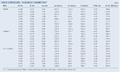
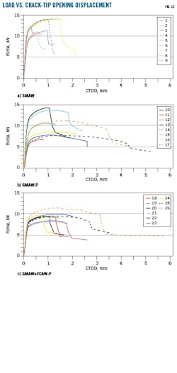
The industrial CTOD requirements of API 1104 and DNV-OS-F101 impose minimum toughness of 0.1 mm and 0.15 mm respectively. Table 8 summarizes the values of Je, Jp, Kc(Jt), and CTOD for SMAW, GMAW-P, and GMAW-P+FCAW welds. The load vs. CTOD areas in Fig. 13 have been calculated up to the maximum load because no pop-in occurred during testing. SMAW welding has a CTOD average value of 0.37 in the filler metal. GMAW-P weld has an average CTOD value of 0.30 in the filler metal, and 0.34 in the HAZ. The lowest measured value, 0.16, was in the filler material. GMAW-P-FCAW-G weld has an average CTOD value of 0.30 in the filler metal with the smallest dispersion. In all cases, CTOD values are more than 0.15 mm. The Kc(Jt) values were also very similar for the SMAW, GMAW-P, and GMAW-P+FCAW welds (Table 8). The good correlation found between CVN and CTOD results was remarkable.
Discussion
The overmatching criterion of API 1104 Standard was met in all the welds studied (Table 7). Mechanical strength of the filler materials (Table 5) greatly influences transverse joint strength and is calculated as the mean of the mechanical strength of the weld passes weighted by their volume.
Joint strength is slightly higher than that of the filler metal, except in the GMAW-P weld (Table 5). The overmatching criterion is met despite the fracture being located at the weld metal of the SMAW+FCAW-G and GMAW-P+FCAW-G welds. The fracture location in the weld metal is normally related to its lower mechanical resistance with respect to the base material. In the case of SMAW+FCAW-G welding, the hardness in the inner part of the tube shows a very significant decrease in the center region of the fill material (Fig. 4b). This hardness gradient generates a metallurgical notch that helps explain fracture of the weld metal.
The mechanical behavior of the welds depends on, in addition to the heat input, the number of passes used. In the case of SMAW+FCAW-G welding, the number of passes is much lower than that used for SMAW welding for a similar joint preparation. This also explains the strong hardness gradient found in the SMAW+FCAW-G weld. The hardness values are related to a combination of grain size and the chemical composition of the electrodes used (Midawi et al., 2015).
In the case of the SMAW+FCAW-G weld, hardness values are similar the SMAW weld. Manual welds are 10% harder than mechanized welds (Fig. 4), despite the larger grain size obtained in manual SMAW welding.
The chemical composition of materials used in mechanized processes E-91T1-M21 4G, E-R70S-6, and E-R110S-G is similar, and produces a higher level of alloy than those used in manual welding. In particular, the E-91T1-M21 4G material used in the GMAW-P+FCAW-G and STT+FCAW-G processes has a lower manganese content. Moreover, it does not contain elements such as niobium, titanium, and zirconium susceptible to forming fine precipitates that pin the grain boundaries. For this reason, GMAW-P+FCAW-G and STT+FCAW-G welds have larger grain size (Figs. 9 and 10) and lower mechanical resistance than GMAW-P welding (Table 7).
The CVN values of the fill material comply with criteria defined in the standards. The CVN are similar in all the welds, except for the high values found in GMAW-P + FCAW weld metal (WM) and the low values found in the SMAW+FCAW WM (Table 7). The latter may be a result of a small defect present in the weld that was not detected by radiographic analysis.
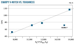
CVN values depend on the mechanical characteristics of the welding materials used in the various processes. In fact, there is a linear correlation between CVN values and the stress-strain area when considering tensile stress, elongation, and hardening values. Thus, the higher the Rm*E*(Rm-Re0,2), the higher the CVN (Fig. 13). The only weld that does not follow this linear relationship is the GMAW-P weld. Its bainitic structure explains the GMAW-P weld’s low CVN despite the high mechanical performance of its filler metal. CVN depends on effective grain size, the number of low angle boundaries, and the phases present in the microstructure.
The most common phase in X80 welding high toughness is the acicular ferrite, although it usually accompanies polygonal ferrite and bainite. Nucleation of granular bainite and the growth of Martensite-austenite constituents decrease fracture toughness in subzones of weldments for different heat inputs. It also is well known that both the chemical composition of the electrode, the number of passes made on a particular weld, and the heat input influence the phases present in welding X80 material.
The use of large-diameter electrodes generates low CVN values due to the formation of large-grain structures. This can explain the low CVN values of the SMAW+FCAW-G weld. The heat input also affects weld toughness. A higher heat input has been related to larger hardness variation and lower impact resistance.
The heat input of all the welds performed in this study was around 1.5 kJ/mm, in the lower range of the values found in available literature for X80. Acicular ferrite has been found in those welds having the lowest heat input values (SMAW and SMAW+FCAW-G), 1.3 and 1.2 kJ/mm, respectively (Fig. 2). Welds in which higher heat input was used, however, GMAW-P (1.8 kJ/mm) and STT+FCAW-G (1.5 kJ/mm), form bainite as the most abundant phase (Table 6). Welder experience is an essential factor in obtaining target values for toughness in the HAZ in which local brittle zones can appear.
The use of FCAW in combination with GMAW automatic and semiautomatic processes in X80 girth welds met the quality criteria described in international standards. However, SMAW+FCAW produces CVN values low enough to potentially induce pipeline failures. An increase in welding speed and current may provide a better mechanical response. This approach will be investigated in a separate study.
In the meantime, mechanized FCAW combined with GMAW welds show similar behavior in terms of hardness, bending, and tensile strength as GMAW-only welds. FCAW-G produces weld mechanical properties that fulfil API-1104 and EN-12732. Manual SMAW+FCAW-G welds fracture in the filler material due to the difference in mechanical behavior between the inner and outer sections of the tube.
Mechanized FCAW combined with GMAW show considerable differences in CVN weld metal values compared with the GMAW weld. These differences are associated with the crystallographic orientation of the grain structure. Structures having many grains oriented according to the cleavage planes present lower Charpy values. The CTOD values for the SMAW+FCAW-G, GMAW-P, and GMAW-P+FCAW-G welds are very similar to each other, and all are above 0.30 mm.
STT + FCAW-G provide high CTOD and CVN toughness. The selection of higher-strength filler material (i.e., E111-T1 instead of E91-T1) will provide even higher weld yield strength.
Bibliography
Adérito de Aquino, F., Yogendra Prasad, Y., and Artur Sanguinetti Ferreira, R., “Evenmatched FCAW process in API 5L X80 steel welded joint,” Materials Research, Vol. 17, No. 2, March-April 2014.
American Petroleum Institute, “API 1104:2013 Standard for Welding Pipelines and Related Facilities,” Jan. 1, 2013.
American Society for Testing and Materials, “Standard Test Method for Measurement of Fracture Toughness,” Sept. 1, 2020.
American Society of Mechanical Engineers, “ASME Section IX-Welding, Brazing, and Fusing Qualifications,” BPVC-IX–2019.
Aydin, H. and Nelson, T.W., “Microstructure and mechanical properties of hard zone in friction stir welded X80 pipeline steel relative to different heat input,” Materials Science and Engineering: A, Vol. 586, Dec. 1, 2013, pp. 313-322.
Bai, F., Ding, H., Tong, L., and Pan, L., “Microstructure and properties of the interlayer heat-affected zone in X80-pipeline girth welds,” Progress in Natural Science: Materials International, Vol. 30, No. 1, February 2020, pp. 110-117.
Berdnikova, O., Pozniakov, V., Bernatskyi, A., Alekseienko, T., and Sydorets, V., “Effect of the structure on the mechanical properties and cracking resistance of welded joints of low-alloyed high-strength steels,” Procedia Structural Integrity, Vol. 16, 2019, pp. 89-96.
British Standard, “BS 7448-Fracture mechanics toughness tests,” 1991-2005.
Chen, X., Lu, H., Chen, G., and Wang, X., “A comparison between fracture toughness at different locations of longitudinal submerged arc welded and spiral submerged arc welded joints of API X80 pipeline steels,” Engineering Fracture Mechanics, Vol. 148, November 2015, pp. 110-121.
Ferino, J., Fonzo, A., Di Biagio, M., Demofonti, G., Spinelli, C.M., and Karamanos, A., “Onshore Pipeline High-Grade Steel for Challenge Utilization,” International Journal of Offshore and Polar Engineering, Vol. 25, No. 4, December 2015, pp. 272-280.
Gook, S., Gumenyuk, A., and Rethmeier, M., “Hybrid laser arc welding of X80 and X120 steel grade,” Science and Technology of Welding and Joining, Vol. 19, No. 1, 2014, pp. 15-24.
Shang, C.J., “The State-of-the Art Long Distance Gas Pipeline in China,” in Kongoli, F., Marquis, F., and Chikhradze, N., (Eds.), Sustainable Industrial Processing Summit (SIPS) 2017, Montreal, Vol. 5., 2017, pp. 486-487.
Han, Y.D., Jing,, H.Y., and Xu, L.Y., “Welding heat input effect on the hydrogen permeation in the X80 steel welded joints,” Materials Chemistry and Physics, Vol. 132, No. 1, Jan. 16, 2012, pp. 216-222.
Hillenbrand, H.G., Kalwa, C., and Liessem, A., “Technological solutions for ultra-high strength gas pipelines,” Europipe GmbH, Ratingen, January 2008.
International Standards Organization, “ISO 12135:2016. Metallic materials — Unified method of test for the determination of quasistatic fracture toughness,” November 2016.
Kong, X., Lan, L., Hu, Z., Li, B., and Sui, T., “Optimization of mechanical properties of high strength bainitic steel using thermo-mechanical control and accelerated cooling process,” Journal of Materials Processing Technology, Vol. 217, March 2015, pp. 202-210.
Lázaro, A. and Dallam, C., “Retos para la industria de unión de tubería Soldadura de X-80 y grados superiores,” Welding and Joining Technologies, Vol. 72, No. 12, December 2001, pp. 23-32 (in Spanish).
Lee, S., Kim, B.C., and Kwon, D., “Correlation of microstructure and fracture properties in weld heat-affected zones of thermomechanically controlled processed steels,” Metallurgical Transactions A, Vol. 23, October 1992, pp. 2803-2816.
Li, T., Zhang, Y., Gao, L., and Zhang, Y., “Optimization of FCAW Parameters for Ferrite Content in 2205 DSS Welds Based on the Taguchi Design Method,” Advances in Materials Science and Engineering, Vol. 2018, Dec. 27, 2018.
Liu, C. and Bhole, S.D., Challenges and developments in pipeline weldability and mechanical properties,” Science and Technology of Welding and Joining, Vol. 18, No. 2, Nov. 12, 2013, pp. 169-181.
Midawi, A.R.H., Santos, E.B.F., Huda, N., Sinha, A.K., Lazor, R., and Gerlich, A.P., “Microstructures and mechanical properties in two X80 weld metals produced using similar heat input,” Journal of Materials Processing Technology, Vol. 226, December 2015, pp. 272-279.
Muthmann, E. and Hillenbrand, H.G., “First X80 pipeline in Italy,” 15th Biennial PRCI/EPRG Joint Technical Meeting on Pipeline Research, Orlando, May 17-19, 2005.
Qi, L.H., Jin, Z.L., Zhang, J.M., Wang, Y.L., Hu, M.J., Wang, Z.C., “Influence factors of X80 pipeline steel girth welding with self-shielded flux-cored wire,” Vol. 33, No. 5, 2017, pp. 592-601.
Santos, T.F.A., Hermenegildo, T.F.C., Afonso, C.R.M., Marinho, R.R., Paes, M.T.P., and Ramirez, A.J., “Fracture toughness of ISO 3183 X80M (API 5L X80) steel friction stir welds,” Engineering Fracture Mechanics, Vol. 77, No. 15, October 2010, pp. 2937-2945.
Shams, S., Hussain, T., Shaikh, S.A., Shams, B., and Bhurgri, J., “Performance analysis of SMAW welding and GMAW-FSAW combined welding for pipeline construction jobs at SSGC, Asia Pacific International Conference on Emerging Engineering, Rahim Yar Khan, Pakistan, Nov. 9-10, 2019.
Shi, Y.W. and Han, Z.X., “Effect of weld thermal cycle on microstructure and fracture toughness of simulated heat-affected zone for a 800 MPa grade high strength low alloy steel, Journal of Materials Processing Technology, Vol. 207, Nos. 1-3, October 200, pp. 30-39.
Singh, M.P., Arora, K.S., Kumar, D., Shukla, K., and Prasad, S.S., “Influence of heat input on microstructure and fracture toughness property in different zones of X80 pipeline Steel weldments,” Fatigue & Fracture of Engineering Materials & Structures, Vol. 44, No. 2, August 2020, pp. 1-16.
Spinelli, C.M. and Prandi, L., “High Grade Steel Pipeline for Long Distance Projects at Intermediate Pressure,” Pipeline Technology Conference, Hannover, Germany, Mar. 28-30, 2012.
Tribe, A. and Nelson, T.W., “Study on the fracture toughness of friction stir welded API X80,” Engineering Fracture Mechanics, Vol. 150, December 2015, pp. 58-69.
Wiebe, J., Scheller, W., Bruns, C., and Schmidt, T., “Impact of FCAW On the Mechanical Properties of Seamless Line Pipe Steels of Grades X65 and X80,” International Offshore and Polar Engineering Conference, Maui, Hawaii, June 19-24, 2011.
Witek, M., “Possibilities of using X80, X100, X120 high-strength steels for onshore gas transmission pipelines,” Journal of Natural Gas Science and Engineering, Vol. 27, No. 1, November 2015, pp. 374-384.
Yang, Y., Shi, L., Xu, Z., Lu, H., Chen, X., and Wang, X., “Fracture toughness of the materials in welded joint of X80 pipeline steel,” Engineering Fracture Mechanics, Vol. 148, November 2015, pp. 337-349.
Acknowledgements
We acknowledge the financial funding for this report provided by Enagas Transporte SAU. The authors would like to personally thank José Manuel Calvo Redondo and Rosario Parra García from the National Center for Metallurgical Investigation’s (CENIM) mechanical testing lab for their support with CTOD tests preparation, the electron microscopy lab of CENIM, and Fernando Sánchez Deza, the certified welder working for Soluciones Industriales y Soldadura (Solysol) who performed the various weld procedures. The authors also like to thank Dean Louloudes, working for Solysol, for help with the submitted document’s English.
The authors
Ricardo Fernández ([email protected]) is a tenured scientist at Consejo Superior de Investigaciones Científicas. He has also served as technical manager the thin films group of the research and development department at Indo International. He holds a degree in physics (1998) and a PhD (2003) from Complutense University, Madrid, Spain. He is head of Metals for a Safe and Sustainable Society (MESO), part of CENIM’s physical metallurgy department. He also leads CENIM’s mechanical testing laboratory.
Angela Lazaro ([email protected]) is chief executive officer at Solysol. She has also served as technical and commercial manager at Lincoln Electric Co.’s Spain and Portugal subsidiary. Lazaro holds a metallurgical engineering degree (1988) from Barcelona Central University, an international welding engineer degree (1998) from International Institute of Welding, and a senior certified welding inspector degree (2015) from American Welding Society. She is a member of American Welding Society (AWS), American Society of Mechanical Engineers (ASME), Spanish Society of Joining & Welding Technologies (CESOL), and Spanish Association of Hydrogen (AEh2).
Carmen Peña Fernández ([email protected]) is a specialized technician at Consejo Superior de Investigaciones Científicas, Madrid. She holds a technical engineering degree from Universidad Politécnica de Madrid. Pena is a specialized technician at CENIM’s mechanical testing laboratory and a member of CENIM’s MESO group.
Juan Manuel López Escobar ([email protected]) is a welding engineer and welding expert at Enagás SA. He has also served as welding engineer at ECA Group and as technical director at Servicontrol. He holds a bachelor of chemical sciences (1993) from University of Alcala, Spain, and an international welding engineer degree (2003) from International Institute of Welding.
Carlos Perez Arnaez is a mechanical engineer at Enagas. Previously he worked as an inspector of materials and equipment for a quality assurance and control consultant in the power and oil and gas industries, before becoming a QA/QC manager in EPC contracts for LNG plants. He holds a bachelor in aeronautical engineering degree (1992) from Universidad Politenica de Madrid and is certified Level 3 in NDT by the Spanish Association of Nondestrucitive Testing.
