Zohr pipeline component installation offers custom deepwater guidance
Loic Baltimore
Saipem SPA
Paris
Pipelay in the deepwater Zohr natural gas field reached 8.6 km/day for 8-in. OD pipeline and 4 km/day for 30-in. OD heavy WT sour service pipeline using S-lay. J-lay of 14-in. OD clad pipelines peaked at 1.4 km/day.
Zohr lies in the Egyptian sector of the Mediterranean Sea. The operator is Petrobel, an operating company jointly held by Eni and state Egyptian General Petroleum Corp., on behalf of Petroshourouk, jointly held by state Egyptian Natural Gas Holding Co. (EGAS) and a contractor comprised of Eni (50% of the contractor’s share), Rosneft (30%), BP (10%), and Mubadala Petroleum (10%).
The field is in Shorouk offshore block in a water depth of 1,400-1,600 m, 180-200 km from shore.
Project execution called for an accelerated production phase (ASU) using six subsea wells clustered around two ROV-operated production manifold tie backs to an onshore plant through six 14-in. OD infield lines, one 26-in. OD main export pipeline, and a 14-in. OD service line. In addition, an 8-in. OD methylene glycol (MEG) line from onshore delivers glycol to the wells. Electrical power, fiberoptic communication, and chemicals are provided to the subsea network via long-stepout umbilical tie back to a new central control platform.
Accelerated production preceded an optimized ramp up phase (ORU) to develop a further four wells, install a 30-in. OD line from shore, and install a further 8-in. OD MEG line for future use.
Saipem executed offshore engineering, procurement, construction, and installation (EPCI) of both phases.
The field was put into production in December 2017, 27 months after reservoir discovery and 17 months after EPCI award due to an early engagement scheme adopted by Petrobel and Saipem. Production reached 2 bcfd in September 2018, following commissioning of the 218-km 30-in. section of line the previous month. EGAS, Eni, and Rosneft expect the field to reach a plateau above 2.7 bcfd by end-2019.
The main factors governing execution were:
- Very tight schedule for first gas (17 months).
- Sour-service requirements for carbon steel gas export lines imposing demanding constraints on material and welding specifications.
- Qualifying subsea equipment (valves connectors and flexibles) for design conditions.
- Design, within 6 months, 600 km of subsea lines to fit.
- Design and install large-diameter spools.
- Landfall construction.
- Preparation and management of a wide offshore construction spread.
- Non-conventional pre-commissioning operations.
The project included 665 km of carbon steel sour-service lines ranging from 30-in. OD × 38.7-mm WT to 14-in. OD × 23.8-mm WT. Sweet service comprised 440 km of 8-in. OD × 20.6-mm WT line, completing the carbon steel lines’ scope.
More than 33 km of 625-clad line (14-in. OD × 20.4-mm WT) and around 80 m of 30-in. OD × 38.7-mm WT pipe respectively connected Christmas trees to manifolds and the 30-in. OD inline valve to the 30-in. OD pipeline-end termination (PLET).
The diversity of lines to be installed, combined with tight schedules, required up to seven laying and installation vessel on the field: Saipem Castorone, Saipem Castoro Sei, Saipem Castoro 10, Saipem FDS, Saipem FDS2, Saipem S7000, and PMS 12 from local subcontractor PMS Offshore Co.
Additional installation factors included the prohibition of copper shoes for sour-service lines, internal visual inspection, and very tight acceptance criteria for clad line girth welds.
Large-diameter lines
As originally conceived, some lines included very heavy and large structures (e.g. 30-in. PLET) which required different types of lay vessels—J-lay or S-lay—for installation. To cope with this constraint, the potential monoblock structure 30-in. PLET that was part of the ORU phase (larger and heavier than the 26-in. PLET designed for ASU), consisting of valve, connector, and integrated mudmat, was split into three substructures including inline components. The first substructure is an inline valve structure (weighing about 90 tons) comprised of a heavy 30-in. valve, a 2-in. precommissioning branch, and a small integrated deployable mudmat.
The second substructure is a smaller PLET, also weighing roughly 90 tons but comprising only the heavy 30-in. connector. The third substructure is a large preinstalled separated mudmat on which the PLET could dock, compliant with flowline expansion and seismic scenarios, completed this portion of the system. The separated mudmat weighs slightly more than 200 tons to account for potential self-penetration.
So the original 220-ton structure, 16 m wide and 26 m long, became three individually lighter and smaller substructures. This allowed the contractor to use the J-lay installation vessel that was already deploying the 30-in. subsea line for this work as well.
The 30-in. lines required 30-in. subsea valves and connectors. The large diameter was out-of-standard for this equipment at the design water depth. Specific qualification testing and fit-up tests guaranteed both design and functionality.
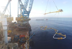
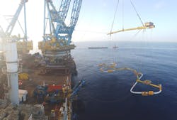
Large three-dimensional spools were designed to not exceed the connector’s loads, tie-in requirements, or installation constraints. They were among the largest and heaviest spools yet designed and installed by Saipem. A specific tie-in concept had to be developed to adapt existing running tools for flexible jumpers to rigid spools. Fig. 1 shows installation of a 26-in. spool.
All procedures and solutions described in this article were developed at Saipem’s Ploiesti Technology Centre (PTC) in Romania. This site is equipped with in-house welding, coating, and non-destructive testing for offshore technologies used on Saipem vessels.
Saipem fully-integrated discrimination approach (SFIDA) technology is an automated technology which integrates different ultrasonic testing methods to optimize inspection on 100% of the weld volume (including root pass on clad lines) and allow inspection of line pipes with heavy WT variations.
Nine months after starting welding procedure qualification testing, all requested procedures were qualified for the offshore campaign, including some prefabrication works.
New electromagnetic acoustic transducer (EMAT) ultrasonic inspection was used during the manual tie-in offshore campaign to help make decisions before weld completion, (i.e. anticipating potential repair and cut out as early as possible to avoid time lost in unnecessary welding). It is based on an electromagnetic mechanism generating ultrasound without contact with the weld. Neither coupling with water nor cooling is needed. EMAT can work up to 300° C. and inspection can take place between passes while welding.
Over a 2-month period dedicated welding training schools set up onboard one of the vessels trained and qualified more than 200 welders in the new method.
Saipem welding system (SWS), with multiple torch welding heads, optimized productivity to vessel and pipeline characteristics. SWS Twin Torch allows high-productivity welding sequences using a pre-set automatic sequence with a patented automatic seam tracking, stick-out control, and autocentering system.
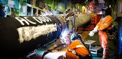
Up to four double-torch welding heads were in use at the same welding station onboard some vessels. This required optimizing every sub-activity at the work station. Fig. 2 shows welding onboard Saipem Castoro Sei during the project.
Sour-service lines
Gas exported was characterised as Sour Region 3. Consequently, the lines were either carbon steel or internally clad with 625 nickel alloy.
For carbon steel lines, the use of copper shoes as a backing medium for welding was prohibited. To cope with the prohibition of copper shoes for sour service pipelines, Saipem developed ceramic-coated steel shoes and combined it with surface tension transfer (STT) for the root pass welding. The STT process was set on SWS heads. This approach doubled welding speed for the root pass with low repair rate during project execution.
Considering the tight weld acceptance criteria applicable to welding cladded pipes, Saipem used its plasma-remelting internal technology (SPRINT) for both internal welding in main procedures and internal touch-up repair on corrosion resistant alloy welds.
This system consists of an internal remelting system, directly connected to an internal clamp, aimed at correcting surface and geometric irregularities detected during internal visual inspection performed with an integrated camera.
The welding technology demonstrated very good welds in all welding positions, especially regarding the root profile. The first use in vertical position occurred during Zohr ORU.
The produced root pass was flat with regular profile, guaranteeing a defect-free layer at internal surface of corrosion resistant alloy materials. The flatness of the profile permitted high fatigue performance for produced welds. It also permitted easier visual inspection and faster automated ultrasonic testing and SFIDA assessment. Saipem subsequently deployed this system on its entire fleet. Savings compared to standard external clad welding are estimated to be almost 50% during project execution, with a low cut out-and-repair rate.
Complex seabed
Several intervention solutions addressed water depth and soil condition. These included pre-lay sleepers, post-trenching, and rock dumping.
Unstable seabed bathymetry required stabilizing the lines against environmental loads, fishing activities, and ship traffic in shallow water and constrained design. To allow laying activities, Saipem had to mitigate lateral buckling and walking, reduce spans and stress, and manage the crossing of cables and other lines.
Design activity sought the best combination of intervention works compatible with project schedule. In particular, intervention for free spans and stress corrections were optimized by a combination of:
- Installation definition.
- Post-trenching.
- Gravel dumping to reduce stresses and free spans.
Crossing existing assets used sleepers protected with gravel berms in shallow water.
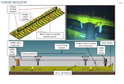
Lateral buckling design identified the need to restrain lateral movement of the 26-in. line sections at crossings. Lateral buckling mitigation devices made from beams with adjustable lateral stoppers were post-installed on the crossing sleeper in deepwater sections (Fig. 3).
The author
Loïc Baltimore is material technologies lead of the subsea engineering and offshore welding NDT and material departments at Saipem. He has also served as welding coordinator at Petromar (2009-11) and material technologies lead at Saipem do Brasil (2014-15). He holds an MS (2008) in mechanical engineering from Arts et Métiers ParisTech and specialized in the international welding engineer program (2007) at the International Institute of Welding, Paris. He is a certified NACE Coating Inspector Level 2.


