Czech crude-oil terminal is in operation
Bretislav Karásek, Miroslav Cibulka
MERO CR, A.S.
Kralupy nad Vltavou, Czech Republic
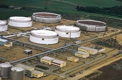
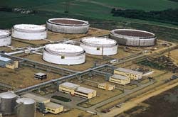
This view of the terminal's tanks shows two of its 600,000-bbl tanks and part of the four 300,000-bbl tanks (Fig. 1).
A major 4.8 million bbl crude-oil terminal near the city of Kralupy nad Vltavou, Czech Republic, began operations in August 1995.
The major objective of building the terminal was to cover oil-supply shortfalls with Czech oil-storage capacities and eventually to blend different crude-oil grades to meet the needs of Czech refineries.
Previously, the Czech Republic (formerly part of Czechoslovakia) depended entirely on crude oil supplied from the former Soviet Union and delivered by the "Druzhba" (Friendship) pipeline.
The Czech government has established a new strategy of energy supply to secure both alternative crude-oil supply independent of Russia and sufficient capacity in its strategic reserves to comply with Western standards.
Completion in January 1996 of a new 344 km, 28 in., 200,000 b/d crude-oil pipeline gives Czechs necessary crude-oil independence. Called the MERO IKL (Ingolstadt-Kralupy line) and operated by MERO CR, the line is linked to the West European TransAlpine (TAL) pipeline system.
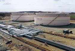
Terminal piping manifold runs past tow 300,000-bbl tanks (Fig. 2).
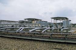
Pipeline-end stations at MERC CR's new terminal (Fig. 3).
MERO CR owns and operates Czech crude-oil pipelines as well as the new $110 million oil terminal (Figs. 1-3). It receives, stores, and blends various crude oils imported both from the West (via TAL) and East (via Druzhba) and ships to three Czech refineries.
The terminal is located where the MERO IKL and Druzhba pipelines link and is connected by the Druzhba pipeline to refineries at Litvínov and Pardubice. A newly constructed 8 km, 14 in., 6,000-b/d capacity pipeline connects the terminal to the nearby Kralupy refinery.
Three stages
Construction of the terminal occurred in three stages.
The first included installation of four tanks of 300,000 bbl each, pumping stations, instrumentation and supervisory control and data acquisition (scada) control center, fire-protection system, cathodic-protection system, terminal piping and central manifold, waste-water treatment facilities, electric network, and all infrastructure needed for the safe operation.
The second and third stages of construction included, respectively, installation of four then two tanks, 600,000-bbl capacity each. The third stage is currently under construction.
Major contractor was a Czech steel company Vítkovice, Ostram (steel plates supplier) cooperating with a number of Czech subcontractors such as Vodní stavby Bohemia, Temelín (civil works) and Hutní montáze Ostrava (construction).
The Czech subsidiary of ABB Lummus Global (formerly Chemoprojekt) provided the project design and instrumentation and scada procurement as well as precomissioning, commissioning, and start-up assistance.
The scada system was designed in cooperation with British Serck Controls.
Tanks
Crude-oil storage is in the 10 tanks on a 200-acre site.
The design was based on oil terminal safety codes, net positive suction head (NPSH) requirements for transfer pumps, and economics.
Each of the four, 300,000-bbl tanks stands 19 m high with a diameter of 60 m; each of the six, 600,000-bbl tanks also stands 19 m high with a diameter of 85 m.
The tanks are constructed on double-shell principle: the outer shell is equipped with hydrocarbon-indication system to retain the tank contents in case of shell leakage.
Likewise, each tank is provided with:
Terminal piping, pumps
The piping system consists of two crude-oil pipeline end stations, one from the MERO IKL pipeline and the other from the Druzhba pipeline. Both stations are equipped with meter skids and pressure-relief elements.
The end stations consist of and are equipped with a pig-chamber, control valve, flowmeter (turbine Brooks type at MERO IKL pipeline and ultrasonic type from Druzhba pipeline), automatic sampler skid (Jiscoot Autocontrol U.K.), pressure and temperature indicator, and pressure relief system (Grove, Voghera, Italy).
Ultrasonic flow meters (Krohne Model UMF 500 EX) with converter (UFC 500 K) and evaluating equipment (UFC 520) is installed on the Druzhba pipeline.
Crude-oil density is measured by a Sarasota FD 800 density meter installed in a by-pass line. It consists of an FD 810 ACST4 sensor producing a frequency signal directly related to density and an HC 900 1P density converter.
The piping system also consists of piping and manifold to enable transfer and/or blend of crude oil from any two of the tanks, and receipt or shipment of crude oil to the off-site pipelines from any tank. Dual lines from each tank connect the tanks to the trunk lines.
The trunk lines are interconnected via a central manifold to transfer pumps and meter skids. The elevation of the piping continually drops from each tank to the transfer pump inlets to provide a "drain-dry" system.
The pipeline has dedicated Worthington (Desío, Italy) vertical transfer pumps at four pumping stations. Four on the tank-to-tank line operate at 750 cu m/hr (52 KPa); two on the line to the Kralupy refinery operate at 920 cu m/hr (2.4 MPa); three on the line to the Litvinov refinery operate at 1,173 cu m/hr (2.5 MPa); two on the line to the Pardubice refinery operate at 192 cu m/hr (60 KPa).
The transfer pumps are designed to handle all crude-oil grades coming to the terminal from Russia, North Africa, or the Middle East.
Fire protection; water treatment
Four principles were incorporated in the design of the fire-protection:
- The terminal is equipped with automatic detection of combustible vapors in selected operating sections.
The objective of the provision is to receive and collect data on any potential danger, such as oil leakage. An automatic fire-alarm signal system is installed on all important sites. - All the tanks, including the space between inner and outer tank shells, as well as all pumping stations are equipped with a fire-fighting system that uses foam to extinguish the fire.
Electrical cable channels and control room are equipped with an automatic carbon-dioxide extinguishing equipment - Hand-operated extinguishing devices are ready to use.
- Each tank is provided with an automatic spray-water tank shell cooling system in case of fire.
Waste-water treatment facilities treat oil-contaminated waters which may occur in emergency sumps and on platforms below process equipment.
These waters are collected by an oily water drainage system and are led into a 5,000-cu m sump tank provided with a floating disc-type oil separator. The water flows by gravity into a de-oiler working on sorption principle.
The oil separated from the water is pumped into a sloptank. The water, after being analyzed, is pumped into the Vltava River or into a fire-water tank.
Control systems
The control system is based on a decentralized control system (DCS) with a doubled system of busbars and processors. The system is supplied from UPS (uninterruptable power supply).
For long distances needing remote units (RTU), the decentralization is designed both in terms of operation and space. Ten RTUs are directly linked to the center, three others by means of modems.
The Serck control system used in MERO terminal consists of:
User software based on Serck Controls application software was developed by ABB Lummus Global.
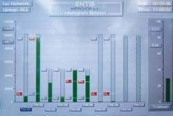
Level monitoring of tanks at the new terminal (Fig. 4).
Tank-level gauging system (Fig. 4; Enraf Nonius and ENTIS software) is independent in terms of operation. But it does transmit major level data as well as high-level warnings to the DCS.
An independent crude-oil balancing system communicates with DCS by means of RS 232.
Enraf instrumentation consists of:
The temperature in the tanks is measured by multiple temperature sensors linked to a level switch which is controlled from the level indicator. Both temperature and level data are transmitted to the DCS control room simultaneously.
High level and high-high level signals are taken from a floating level switch Magnetrol XF 10, XA 15, XB 15, etc.
Oil level in the tanks is further measured by a hydrostatic pressure method that uses Fisher-Rosemount 1151 LT-5 instruments and by floating level indicators Ekorex, mainly used for local indication, equipped however with limit contacts and with 0-100 ohm resistance transmitter for remote level indication.
Pressure and differential pressure are measured by electronic instrumentation with 4-20 ma outlet signal and with local indicators. Fisher-Rosemount instrumentation, Models 2088 G and 1151 DP, are applied for pressure and differential-pressure instrumentation.
Temperature measurement in terminal piping is provided with electrical resistance thermometers Pt 100 in 3 or 4- wire connection.
The Authors
Bretislav Karásek is the board vice-chairman and technical director of the Czech oil transportation company MERO CR. He is in charge of technical development projects from design to start-up operation. Before joining MERO CR in 1993, he had been technical director at Kaucuk Kralupy, a large Czech refining and petrochemical company.Karásek holds a master degree in chemical engineering and macromolecular chemistry from Chemical & Technical University Prague. He has been awarded a title of top specialist in chemical engineering from the Ministry of Industry.
Miroslav Cibulka is a specialist in instrumentation and advanced control systems at MERO CR. He worked for Kaucuk Kralupy more than 30 years before joining MERO CR. Cibulka holds a masters degree in electrical engineering from the Technical University of Prague.
Copyright 1997 Oil & Gas Journal. All Rights Reserved.
