Technology advances keeping LNG cost-competitive
Edward J. Bellow. Jr., Fouad P. Ghazal, Alan J. SilvermanLNG plants, often very expensive in the past, will in the future need to cost less to build and operate and yet maintain high safety and reliability standards, both during construction and operation.
Mobil Technology Co.
DallasStephen D. Myers
Mobil Oil Corp.
Fairfax, Va.
Technical advancements, both in the process and in equipment scaling, manufacturing, and metallurgy, will provide much of the impetus for the improved economics.
Although world energy demand is predicted to grow on average of about 2% annually over the next decade, LNG is expected to contribute an increasing portion of this growth with annual growth rates averaging about 7%.
This steep growth increase will be propelled mainly by the environmentally friendlier burning characteristics of natural gas and the strong industrial growth in Asian and Pacific Rim countries.
While LNG is emerging as the fuel of choice for developing economies, its delivered cost to consumers will need to stay competitive with alternate energy supplies if it is to remain in front.
Development
Origins of LNG manufacturing technology can be traced to the low-temperature cryogenics used in air liquefaction developed in the 1920s.
The first application of LNG was in the early 1930s in the recovery of helium from natural gas for strategic purposes (use in military balloons).
The process was based on liquefying the hydrocarbon components of natural gas, leaving behind helium for recovery as a gas. After helium extraction, the LNG was revaporized and sold as pipeline gas.
In 1939, Hope Natural Gas Co., subsidiary of Consolidated Natural Gas Systems, built the first plant which actually liquefied natural gas and stored LNG for later use.
Then in 1941, the plant was built that all in the LNG business remember.
The East Ohio Gas Co. built a peak-shaving plant in Cleveland, Ohio. Its purpose was to manufacture and store LNG during low demand to supplement regular natural-gas supplies when in high demand.
After 21/2 years of successful operation, an additional storage tank was added. This new tank failed in 1944 because the metallurgy was unsuitable for cryogenic temperatures. The failure resulted in a major fire and much property loss.
Although subsequent applications solved this problem by using higher Ni steel or cryogenic aluminum, it was this incident that arrested the growth of the LNG industry for 20 years.
In 1965, Alabama Gas and Transcontinental Gas Pipeline Corp. became the first two companies to commission LNG plants in the U.S. after the Cleveland incident.
With the technology reestablished, other companies followed suit; now there are currently more than 100 peak-shaving plants in the U.S. alone.
Also in the early 1960s, major investments started occurring in LNG "base-load" plants. These are commercial-scale plants for liquefaction of natural gas for export to consuming markets.
The Camel plant in Arzew, Algeria, was the vanguard of such plants with a total capacity of 250 MMscfd (three trains). LNG product was exported to the U.K. with the first cargo shipped on Oct. 7, 1964. This plant is still operating today.
Plants were later built in Skikda, Algeria, Marsa El Brega, Libya, and Kenai, Alaska. The product from the Algerian and Libyan plants went to supply the French and Italian natural gas markets, while the Alaskan plant product went to Japan.
Throughout the 1970s, LNG manufacturing experienced a rapid growth through base-load plants, most of which were installed in Southeast Asia.
This growth was initially fueled by Japan, then Korea and Taiwan, whose rapidly growing appetites for LNG were driven by strategic priorities to diversify their energy-supply sources and to alleviate air pollution in their densely populated cities.
Plants with capacities ranging from 850 to 1,200 MMscfd each were built in Lumut (Brunei), Arun and Badak (Indonesia), Das Island (Abu Dhabi), and Bintulu (Sarawak).
At the same time, the Algerian plants in Arzew and Skikda added additional LNG trains and a four-train plant was built in Marsa El Brega (Libya) to meet burgeoning demand from France, Italy, and Spain. The economic downturn in the 1980s brought on by the rapid increases in crude prices slowed LNG growth somewhat.
Economies began to strengthen, however, and sharp upturn in industrial development in much of Asia, coupled with increasing global environmental concerns, have catapulted LNG to the forefront of new and replacement energy growth worldwide.
As a result, the 1990s have brought many new LNG projects to fruition with major installations in Qatar, Nigeria, and Oman as well as several existing plant expansions.
This growth forecast puts LNG as the leading energy source in supplying an increasing share of new and replacement energies worldwide well into the 21st Century.
LNG process, developments
Produced natural gas is unsuitable to be liquefied because it contains impurities that would hamper or damage the liquefaction equipment. Thus, raw natural gas must undergo several operations to remove the contaminants that would freeze, plug, or corrode the cryogenic facilities being liquefied.
The essential steps are illustrated in Fig. 1 [29710 bytes]: entrained liquid separation, mercury removal, treating for removal of CO2 and sulfur compounds, dehydration, and C5+ removal. The purified natural gas is therefore mainly liquefied methane with smaller amounts of ethane, propane, butane, and nitrogen.
The heart of the process is the liquefaction step wherein natural gas is chilled to about -258° F. for conversion into a liquid that can be stored and shipped at atmospheric pressure.
This liquid, LNG occupying only about 1/600 the volume of the purified natural gas, is the key to the success of LNG, since it becomes economically attractive to ship long distances to areas of high energy demand.
The first two base-load LNG plants relied on the Cascade Refrigeration (CR) cycle for liquefaction. In this cycle (Fig. 2 [34758 bytes]), three refrigerants-propane, ethylene, and methane-were compressed, cooled, then flashed, each at three different pressure levels, against the treated natural-gas feed in a cascade arrangement.
The cycle is easy to design, the properties of the refrigerants are well known, and the heat-exchange design straightforward. This process has a relatively large number of compressors and exchangers and requires ethylene makeup be imported from an outside source.
A late development in CR cycle plants has been the recent announcement of a plant using a modified CR process in Trinidad.
To reduce the number of compressor and heat-exchanger trains, the Mixed Refrigerant (MR) cycle was developed and first used in Libya's Marsa El Brega plant.
In this cycle, a single refrigerant made up of nitrogen, methane, ethane, propane, butane, and pentane, is compressed, cooled, then flashed, either at a single or double pressure level, before cooling the treated natural-gas feed in a multistream exchanger (Fig. 3 [33417 bytes]).
MR make-up and compression levels were tailored to match the needs associated with the feed-gas composition and plant-inlet conditions.
The latest development in the liquefaction cycle is the Precooled Mixed Refrigerant (PMR) cycle. This combines the simpler refrigerant-train configuration of the MR cycle with the efficiency of the CR cycle.
In the PMR cycle (Fig. 4 [31575 bytes]), either a single component or a mutlicomponent refrigerant is used to precool the mixed refrigerant before the latter is flashed and exchanged against the treated natural-gas feed.
This cycle, using a single-component precool refrigerant (propane) has been used in the majority of the latest LNG-plant designs. The first use of a dual-component precooling refrigerant in a PMR will be in Nigeria's first LNG plant currently under construction at Bonny Island.
Treating processes
The objective of the treating operation is the removal of mercury to the parts-per-billion (ppb) level, and CO2, sulfur compounds (H2S, COS, and mercaptans), and water vapor down to the parts-per-million (ppm) level.
This is generally accomplished with use of a combination of wet and dry processes: carbonate and/or amine solutions for removal of CO2 and sulfur compounds and by molecular sieves for removal of water vapor and mercury.
Both require regeneration of the solvent(s) and the adsorbent beds either continuously (wet systems) or cyclically (solid systems). Spent mercury-sieve beds are not regenerated but are replaced with fresh material.
The process configurations for these systems have not changed much over the past 30 years and most of the developments in this area have concentrated on developing proprietary solutions and molecular sieves with improved absorptivity/adsorptivity and selectivity.
The resultant benefits were reduced equipment sizes and reduced regeneration-energy requirements. Also, improvements in the analytical methods for measuring mercury content of natural gas in the ppb range have enabled detecting and quantifying the presence of this element in these very low ranges.
This in turn helped in the fight against mercury attack of the aluminum used in the cryogenic heat exchangers.
It should be noted here that the mercury-removal process, which involves chemical adsorption or catalyzed reaction, must be custom-designed for each new LNG plant because its effectiveness is influenced by the anticipated gas compositions and operating conditions.
Equipment developments
The major technical developments in the LNG industry have been in maximizing the capacity of the major equipment in the process plant to improve individual-train capacity.
The drive has been and will continue to be economy of scale which translates into reduced total plant cost per unit LNG produced. This has been achieved while even improving equipment reliability and performance.
The major plant units are the acid-gas absorber in the treating unit, the main heat exchanger in the liquefaction unit, and the centrifugal compressors on the precooling refrigerant and the mixed refrigerant.
Main heat exchanger (MHE)
The MHE is the core of the liquefaction section; it provides the medium for cooling and liquefying the treated natural-gas feed by exchange against separate streams of vapor and liquid mixed refrigerant.
To attain the close temperature approaches required in this heat-exchange phase, true counter-current flow is required.
For this reason, and considering the absence of fouling potential in this service, initial LNG plant designs used a finned plate exchanger made of aluminum (most cost effective material at the cryogenic temperature levels).
These exchangers were heavily insulated and enclosed in a box that gave them the "cold box" name.
Design pressure and fabrication considerations limit the size of individual plate exchangers. Desired train capacity is achieved by combining several units in parallel at the cost of increased piping, valving, and instrumentation.
Also, care must be taken in the design of the distribution system to ensure proper phase distribution for the various streams.
Alternative to the plate and fin exchanger is the "spiral wound" exchanger. This exchanger consists of thousands of aluminum tubes wound in several layers, separated by spacer wires, over a central core called the mandrel.
The space between the tube layers provides the flow path for the shellside flashed mixed-refrigerant stream used to cool the treated natural-gas feed and the high-pressure mixed refrigerant streams on the tube side. (The tube side provides for several separate fluids flow.)
The exchanger is essentially a "shell-and-tube" design with manholes in the top and bottom headers which permit access for plugging tubes that may develop leaks.
Developments in the design and fabrication areas enable construction of single units measuring up to 14 ft diameter and 180 ft tall that fit train capacities of up to 600 MMscfd (4 million tons/year) in current facilities.
Compressors, drivers
As mentioned earlier, the liquefaction process has evolved from the CR cycle to the MR cycle mainly for the benefit of reduced compressor and exchanger trains for a given train capacity.
The philosophy of reducing the number of main equipment units, by maximizing their sizes, has also motivated the drive for larger compressor/driver units for both the precooling mixed refrigerant and the liquefaction mixed refrigerant.
In addition to the drive for larger machinery size, there has been a shift from the steam turbine to industrial gas turbine as the compressor driver.
The shift was motivated by reduced capital cost resulting from the absence of steam generating and boiler-feed-water treating facilities associated with the steam turbine.
The shift was also supported by increased reliability, operating range, and operating experience of the industrial gas turbine.
Although most existing plants are equipped with steam turbines, the preferred driver until recently has been the dual-shaft industrial gas turbine (the preference over the single shaft machine stemming from the ability to control the speed of the power turbine independently from that of the gas generator).
Both the Arun and Northwest Shelf plants have had good operating experience with dual-shaft gas turbines (GE Frame 5 in both installations).
Current projects (Ras Laffan in Qatar and Bonny in Nigeria), however, are installing GE Frame 7 single shaft gas turbines because of:
- A 15-25% reduction in specific capital cost ($/mw) as a result of using fewer larger turbines; Frame 7 has an ISO rating of about 80 mw compared with 28 mw for Frame 5.
- A 10-15% improvement in specific fuel consumption.
Regarding compressors, maximum suction volumetric rate that can be handled (less than 200,000 actual cu m/hr) currently limits single casing capacity.
The alternatives of using axial machines, however, larger impeller centrifugal machines not yet proven in baseload LNG service (but proven in other hydrocarbon processing installations) or centrifugal machines with dual flow suction arrangements, could increase the suction volumetric rate limit to 300,000 actual cu m/hr.
The benefit of course is a potential reduction in the number of machines required per train.
Pressure vessels
The main developments in pressure vessels have been in coming up with novel tower internals, whether packings or trays, for increased tower capacity and improved contacting efficiency.
The benefits are smaller diameter towers with thinner walls and lighter weight. The main beneficiary of these gains is the absorber tower in the acid-gas removal unit which has been limited in size in past projects by the capability of available construction equipment for its erection.
More economy of scale
Considering that liquefaction technology is mature, future technological advancements in LNG manufacturing would most likely be focused on increasing the single-unit capacity of the major equipment to reduce the number of such units, that is, gaining from economy of scale.
Improvement in equipment capacity would have to be achieved while maintaining and improving safety, efficiency, reliability, and maintainability.
Further developments of proprietary solvents/adsorbents will continue the progress in improving efficiency and selectivity of contaminants removal with the benefits of reduced capital and operating costs.
The industry is also looking at smaller units in either spiral or cold-box cryogenic designs for niche applications.
Commercializing floating LNG technology will probably be a major new frontier for the LNG industry.
This concept has been studied for many years. Recently the industry has developed a renewed interest in such an approach in an effort to reduce the costs and schedule of LNG projects. Industry consortia such as the Gas Utilization Research Forum and several contractors are continuing to investigate alternative configurations and sizes of floating LNG plants.
Mobil has an ongoing research and development program in floating LNG and has made a major breakthrough in technology that offers the potential for significant capital and schedule improvements over conventional onshore LNG construction.
Commercializing floating LNG technology will probably be a major new technology frontier for the LNG industry.
These new technologies, coupled with an increasing demand worldwide for cleaner burning, environmentally friendlier fuel, will be the main foundation for monetizing remote off-shore gas reserves.
Sources consulted
Coyle, D.A., Durr, C.A., De La Vega, F.F., Hill, D.K., Collins, C., "LNG Plant Design in the 1990s," proceedings of the 74th GPA Annual Convention, pp. 177-82.
Geist, J.M., "Refrigeration cycles for future base-load LNG plants need a close look," OGJ, Feb. 4, 1985, pp. 56-60.
Keens, D., "Engineering Progress in Methane Liquefaction," Proceedings of the 7th International LNG/LPG Conference, Houston.
Liu, Y.N., Edwards, T.J., Gehringer, J.J., Lucas, C.E., "Design Considerations of Larger LNG Plants," Proceedings of the 10th International LNG/LPG Conference, Kuala Lampur.
Nagelvoort, R.K., Poll, I., Ooms, A.J., "Liquefaction Cycle Developments," Proceedings of the 9th International LNG Conference, Nice.
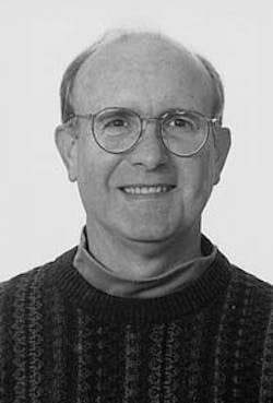
Edward J. Bellow is a consultant in LNG and plants for Mobil Technology Co., Houston. He was process engineering manager for Mobil Research & Development Corp. 1986-1995 and manager of Mobil's Torrance, Calif., refinery's technical department 1979-1986. Bellow holds a chemical engineering degree (1963) from Texas A&M University.
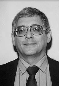
Fouad P. Ghazal is an advanced engineering associate with the LNG group in the surface engineering department of Mobil Technology Corp. He holds an MS from the Massachusetts Institute of Technology, Cambridge, Mass., and a BS from Cairo University.
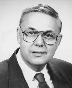
Alan J. Silverman is manager of LNG and plants for Mobil Technology Co. He has served as operations executive and offshore technical services manager for the P.T. Arun LNG Co. 1991-1995, manager of exploration and producing process engineering for Mobil Research & Development Co. 1984-1991, and group leader and senior process engineer for Mobil Research & Development Co.Silverman holds a chemical engineering degree (1965) from City College of the City University of New York.
Stephen D. Myers is a strategic business advisor for Mobil's Upstream Coordination Council, Fairfax, Va. He was formerly reservoir engineering manager in Mobil's Denver office 1988-1990 and an engineering manager for Mobil Oil Indonesia 1984-1988. Myers holds BS and MS degrees in petroleum engineering and a PhD in engineering, all from the University of Oklahoma. He is also a member of the SPE.
Copyright 1997 Oil & Gas Journal. All Rights Reserved.


