Multilateral casing-exit technology eliminates floating rig heave
Dean E. Gaddy
Drilling Editor
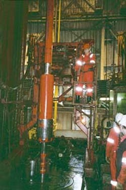
The lower secondary-cylinder of the ROPC tool slowly repositions the mill back to the point where milling last stopped in case the tool is lifted off-bottom. It has a secondary feed rate which prevents bottom hole impacting (Fig. 1).The first-ever multilateral casing exit from a semisubmersible used an innovative rate of penetration control (ROPC) tool to neutralize vessel heave. This tool was pivotal in milling through the casing and liner positioned at the juncture of a multibranched well, and was instrumental in reestablishing contact with the main well bore.
Until recently, these types of operations were ill-suited for floating rigs because of wave-induced heave.
Although floating rigs have compensators, there is still a degree of residual heave that applies cyclic weight fluctuations to mills and drill bits. These fluctuations bounce the mill or drill bit on-and-off the bottom of the hole with weight oscillations as great as 5 tons.
Although this range does not normally hamper drilling, it impedes milling because of the sensitive weights needed to time-mill. In a time-milling operation, the weight-on-bit (WOB) requires a "light touch" that is almost imperceptible on the weight indicator.
Rate-of-penetration control tool
The ROPC tool (Fig. 1 shown above) was developed by Weatherford for use in the Troll West Gas Province operated by Norsk Hydro. It is 50 ft long and is comprised of an upper main cylinder and a lower secondary cylinder (Fig. 2 [14,031 bytes]). It is a mechanically operated device that eliminates heave effects during the milling operation.The tool is operated by landing it on a wear bushing in the subsea wellhead. The lower end has a large marine-swivel thrust bearing and external flow slots for mud circulation. WOB variations are eliminated once a specified amount of slack-off weight is applied to the tool.
According to Mike Luke, senior R&D designer for Weatherford, it is strictly a load-operated tool. It does not matter how much the rig is moving up-or-down, it is only necessary to ensure that there is enough slack-off weight placed on the shoulder of the wellhead to offset cyclic heave. The tool then becomes a fixed reference for controlling the ROP.
The ROP is precisely controlled as long as the slack-off weight is maintained within the tool's operating ranges. Penetration rates are achieved by selectively adding-or-removing weight to the tool. The slack-off weight is supported by a volume of hydraulic fluid which responds to load fluctuations according to the amount of rig heave.
The tool controls ROP through a group of flow regulators located in the main upper cylinder. These regulators maintain a constant volume flow-rate of hydraulic fluid across the piston. Thus, penetration rates become insensitive to heave because the cylinder's pressure can fluctuate up and down while the piston moves at a constant speed.
The ROPC tool has multiple penetration rates that can be changed by simply increasing or decreasing the slack-off weight. Thus, the tool is able to accommodate a wide range of milling conditions.
The main upper cylinder has a long stroke with a uni-directional downward feed rate. Therefore, picking the tool up off-bottom will not cause it to stroke back to its original position. In order to restroke it, it is necessary to pull the ROPC tool to the surface and reset it.
The lower secondary-cylinder is a retractable, dual-action device which controls on-bottom positioning. It is designed to prevent bottom hole impacts through a secondary feed rate. This eases the mill back to its original position at a rate that will not damage it.
Picking the tool up off-bottom recocks the lower cylinder so that it is ready for another on-bottom landing. In the event milling operations are temporarily stopped, the tool can be lifted off-bottom and set back down without any change in original position of the mill. Once back on-bottom, the main upper-cylinder takes over and milling resumes.
Multilateral milling
Weatherford and Halliburton Energy Services have cooperated in developing the trademarked MLS (multilateral system) 3000 technology for multilateral casing exits. The MLS 3000 system consists of:- Installing and orienting a whipstock
- Window milling off of a hollow whipstock
- Drilling a lateral extension
- Completing the lateral section
- Cementing the lateral back to the parent borehole
- Reopening the parent borehole
- Installing a reentry diverter for each well-juncture.
Milling phases
The first phase of the milling system required three bottom hole milling assembly (BHA) runs designed specifically for exit milling off of a hollow-concave whipstock.The first BHA utilized a three-bladed starter mill that created about an 80 in. long extended window above and below the tip of the whipstock (Fig. 3 [37,740 bytes]). This was achieved without the mill ever contacting the whipstock rails.
The ROPC tool was used on this run and restroked at the surface after the section was completed. According to Doug Durst, senior R&D engineer for Weatherford, Hydro did not originally intend to run the ROPC tool during the first phase. However, concerns of kicking-off the whipstock into unconsolidated sands provided an opportunity to utilize the tool's functionality.
Durst explained that in the event the mill was spaced out high in relation to the whipstock, it was preferable to use the tool's high-speed rate to quickly reach the bottom hole cutting surface. In other words, "the driller could run in the hole very quickly, and by closely monitoring the torque, he would immediately know when bottom had been found. Then it was simply a matter of reducing the applied slack-off weight to achieve the desired milling rate."
The second BHA had a newly designed window mill which was used to capture a cored section of casing. The mill had a short, tapered cutting structure followed by an extended body which ran along the whipstock's rail (Fig. 4 [38,488 bytes]). The extended body acted as a stabilizer which minimized the cutting structure's contact with the whipstock. With the ROPC tool eliminating the rig's heave effects, these features greatly reduced the risk of the BHA cutting into the whipstock itself.
The third BHA run was a stiffer assembly than the second BHA run. This ensured an optimal window length by minimizing the possibility of an early exit. It consisted of standard window and watermelon mills (Fig. 5 [22,222 bytes]) which were used to complete the window exit out past the end of the whipstock. There was no need for the ROPC tool on this run because it was more of a drilling process.
After completion of the first phase, a directional drilling assembly was used to extend the multbranched leg of the well to total depth. Then a liner was installed across the hollow whipstock into the lateral section of the well.
Parent bore hole reentry
The purpose of the second phase was to reenter the parent well. It consisted of four BHA runs. The first initiated an entry into the liner/cement juncture. The second opened up the hollow whipstock and completed the full length pilot hole passageway. The third completed the full through bore opening of the hollow whipstock, and the fourth eliminated a plug within the whipstock packer.Prior to the first BHA run, an anchor packer and a mill guide were run to a defined depth with the guide face oriented approximately 170-180° from the whipstock face. This provided a guide that ensured that the pilot hole's milling direction would be maintained in the first and second BHA runs.
Pilot hole
The first BHA run of the second phase initiated a pilot hole by milling a ledge into the liner (Fig. 6 [34,235 bytes]). This used a skirted mill and mill guide and provided a point from which the nose mill of the second BHA could safely track underneath the liner.The ROPC tool was essential for this stage and was the original intent for developing the tool.
"Milling through liners or casing at shallow angles requires controlled time-drilling," Luke explained. "You cannot tolerate the high WOB fluctuations that you would get without this tool because of the rig heave in rough seas."
According to Durst, the most critical application in the whole system was the skirted pilot-hole mill run. "The success of the reentry hinged on the proper depth positioning and orientation of the mill guide relative to the whipstock," he said, "followed by controlled time milling needed to create the initial ledge into the liner/cement sheath."
Durst said that the weight applied to the mill during this run was almost negligible until the ledge was created. Then the driller increased the load by varying the slack-off weight.
Once the ledge was created, reentering the pilot hole underneath the liner for the subsequent BHA run had a high degree of success because of the stabilization from the mill guide coupled with the time-milling capability provided by the ROPC tool.
The second BHA run completed the pilot-hole passageway through the hollow whipstock by using a round-nose mill (Fig. 7 [40,188 bytes]). It milled through a filler material in the hollow of the whipstock that was used to isolate the parent bore from the lateral while completing phase one. At this point, the anchor packer and guide mill were removed, along with the ROPC tool.
The third BHA run consisted of a full-gauge guide mill with 30 ft of laced collar mills which were used to complete the full through-bore opening of the hollow concave whipstock. An extended stinger was landed within the pilot hole and guided the guide mill assembly through the whipstock.
The fourth BHA run was needed to eliminate a metal plug positioned just below the hollow whipstock in order to provide a full passageway into the parent well bore.
At the end of this phase, the milling was completed and the parent and lateral boreholes were prepped for planned completions.
Whipstock systems
The retrievable hollow whipstock is a hydraulically set, nonhinged whipstock. It serves four key roles:- Effect the window casing exit
- Guide the lateral drilling assemblies
- Direct the liner into the lateral hole section
- Provide an access in order to reestablish contact with the parent borehole.
- Running a solid whipstock
- Milling the window and drilling the lateral
- Retrieving the solid
- Installing the hollow whipstock
- Running a liner into the lateral
- Completing the lateral
- Setting a packer in the lateral
- Running a guide assembly and milling the parent well pilot hole
- Running a round nose mill
- Completing the pilot the through the hollow whipstock.
- Running a hollow whipstock
- Milling the window and drilling the lateral
- Running a liner into the lateral
- Cementing the lateral
- Running a guide assembly and milling the parent well pilot hole
- Running a round-nose mill
- Completing the pilot through hollow whipstock
- Running a packer-plug mill.
Copyright 1997 Oil & Gas Journal. All Rights Reserved.

