Mechanical properties critical to pipeline project economics
Kuruvila Varughese
Herberts-O'Brien Inc.
Houston
The role played by pipeline coatings' mechanical properties (flexibility, impact resistance, adhesion, and abrasion resistance) in controlling the economics of construction is not fully understood.
These properties are distinct from coatings' more important corrosion-protection properties: cathodic disbondment, surface wetting, chemical adhesion, oxygen and water-transmission coefficients, and hot-water absorption.
A clear understanding of corrosion coatings' mechanical properties will keep their role in project economics in proper perspective. This first of two articles addresses coating's flexibility; the conclusion will discuss the remaining three properties.
Coating's role
External corrosion protection for pipelines consists of coating and cathodic protection. Its success greatly depends on the coating's ability to provide a barrier against oxygen and water and to work with the cathodic protection.
For internal protection, however, success mainly depends on the coating's ability to prevent the corrosion-causing ions from reaching the pipe surface.
Although corrosion protection is the major factor in determining the type of pipeline coating,1 mechanical properties also influence this choice because of their role in controlling the economics of pipeline construction.
All groups involved in pipeline activities-chemists who develop the coating, design engineers who specify the coating, and construction engineers who install the pipeline itself-work toward constructing the pipeline within the specified time and ensuring it operates for its design life.
Because they are involved in different disciplines, however, each has different and potentially conflicting priorities.
To complete the pipeline successfully, all must recognize the final objective and accommodate the priorities of the others.
The chemist who originally develops the coating for a specific project should foresee the application of the coating beyond laboratory tests.
The pipe line construction engineer must recognize the effect of the construction activities on the integrity of the coating. To achieve this recognition, a clear understanding of the laboratory test method is necessary correctly to correlate the expected performance results to the field limitations.
Similarly, the pipeline design engineer should appreciate the long-term performance capabilities and installation limitations of the particular coating system.
Flexibility
Among pipeline coating's mechanical properties, flexibility is one of the most important. It affects the construction activities in terms of expense, time, and installed coating integrity. Everyone involved with the pipeline must understand the role that this property plays.
Field bending
Flexibility is affected by temperature, coating thickness, and substrate thickness. An understanding of the effect of these variables and an appreciation of their importance are imperative for those involved in constructing oil and gas pipelines.
Flexibility is a measure of the coating's ability to resist mechanical damages when stretched. This property is critical in pipe line construction because it will decide the field-bending limits of the coated pipe.
This ability of the coating to withstand bending during pipeline construction influences the number of prefabricated fittings. This will affect cost because fittings are among the most expensive items in the pipeline.
Reducing the number of fittings will therefore reduce the overall cost.
One way is to bend the factory-coated line pipe in the field "as and when needed." This is possible only if the coating is flexible enough to withstand the field-bending requirements.
Elongation
Flexibility of the coating is usually expressed in three different units: pipe diameter (PD), degrees of bend per pipe-diameter length (°/PDL), and strain in percentage of elongation (%E).
Pipe diameter is defined as PD=R/d, where R is the radius to the neutral axis of the circle to which the pipe can be bent to the maximum limit without any coating damage and d is the OD of the pipe (Fig. 1 [16633 bytes]).
Degree/PDL is the maximum bend (in degrees) to which the pipe can be subjected over a length of 1 diameter, the diameter length. The diameter length is defined as L/D, where L is the length of pipe used for bending and D is its diameter.
Bend strain is the measure of the maximum possible expansion of the coating expressed as percentage of elongation (%E).
This expression usually poses no confusion.
The other two units, however, confuse most in the field. Therefore, a firm understanding of the interrelationship of these three units is essential for correlation of the laboratory and field data which are often reported in any one of the three units mentioned.
The interrelationship of these three units can be understood from the following calculation:
In the concept of pipe bent into a circle (Fig. 1 [16633 bytes]), the neutral axis runs along the center line, and the circumference of the neutral axis equals the original pipe length before bending. This concept has been used by others.
During the bending action, the coating on the external side expands; the elongation (E) can be calculated as follows:
E = (outer circumference 2 neutral axis circumference)/ neutral axis circumference
=2pi(R=d/2)-2piR / 2piR
=d/2 /R
%E =50d/R
Since d/R is by definition 1/PD, then %E = 50/PD. Bend (°/PDL) is calculated as total bend degrees/circumference of neutral axis in increments of pipe diameter.
Because the maximum possible bend is 360° for the entire circumference, °/PDL = 360/[(2pR)/d] = 360d/(2 x 3.14 x R) = 57.3d/R = 57.3/PD.
With the following flexibility equations, flexibility expressed in any unit can be converted to other units:
°/PDL = 57.3/PD (1)
PD = R/d (2)
%E = 50/PD (3)
Test methods
There are two common laboratory test methods to measure the flexibility of pipeline coatings: the four-point bend test and the mandrel bend test. Laboratory-prepared test straps or straps extracted from coated pipe are used as test specimens.
Four-point test
The four-point bend test is used to determine the absolute flexibility of the coating.
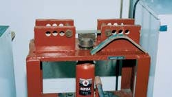
In this method, the test specimen is confined to two pins. It is then bent with a movable block that pushes the sample upwards from underneath (Fig. 2 - below).
In this four-point bending test machine, a specimen is mounted on the machine for a test and a tested sample sits to the right (Fig. 2).
The bending is stopped at the first sign of cracks or stretch marks on the coating. The test specimen is removed, and the neutral radius of the bend (R) calculated by measurement of the inner radius (r1) or the outer radius (r2) of the bend (Fig. 3 [9492 bytes]).
Either radius can be used for calculating the neutral radius (R; Fig. 1), where: R = r1 + t/2 or r2 2 t/2. Here, the diameter (d) in the original Equation 2 is replaced by the effective thickness (total thickness of the substrate and the coating) of the test specimen (t; Fig. 3).
Mandrel bend test
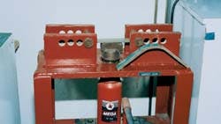
The mandrel bend test method is different from the four-point bend test. In this method, the coated specimen is bent over the various mandrel shoes, each having specific radii and arc dimensions (Fig. 4 - below).
Beside this mandrel bending machine are different fusion-bonded epoxy coated samples (after bending) and shoes (upper left) with different radii (Fig. 4).
The coated specimen is bent only to a specific value for a pass-or-fail criterion which is different from the four-point bend method in which the maximum flexibility of the coating is evaluated. Details of the test procedure can be found elsewhere.3
The following equation calculates flexibility:
PD = Rm + t/2 /t (4)
where: Rm = radius of the mandrel
t = effective thickness of the coated specimen
Even though PD and °/PDL are the units preferred by pipeline engineers, the flexibility in percentage of elongation is the preferred unit for coating chemists.
The percentage of elongation (%E) can also be expressed as %E = 100t/2Rm+t or 100/2PD = 50/PD (Equation 3).
Another equation3 for flexibility that uses the mandrel bend machine is Rm = (57.3t/s) 2 (t/2) in which s is the strain calculated in °/PDL.
Influences
Temperature and coating thickness have considerable influence on the flexibility of the coating.
Usually, colder temperatures adversely affect the flexibility, irrespective of the coating type. The degree of change varies, however, with the coating type.
Generally, the data sheet of each system gives the flexibility dependence on temperature.4 From the flexibility values of several types of fusion-bonded epoxy (FBE) coatings at various temperatures, it is reasonable to assume a reduction of up to 25% when the temperature changes from 73° F. to 0° F. for FBE.
Flexibility is also related to coating thickness, and it is therefore important to note the flexibility value of the coating at a specific thickness. Since flexibility is related to effective thickness of the specimen which includes the coating thickness, any change in the coating thickness will potentially change the flexibility value.
From Equation 4, it is clear that as coating thickness increases, the flexibility decreases. The effect of the coating thickness on flexibility is most dramatic when thin layer coating systems on thin substrates are considered.
Flexibility results obtained by either the mandrel bend or the four-point bend method also depend on the physical condition of the test specimens. All tests are conducted with the test coupon placed in the bend machine with the coated surface to be tested facing up.
Although the test coupons prepared in the laboratory will give accurate results consistently, the results obtained with samples extracted from the pipe can be inconsistent and erroneous because of variations in sample preparation.
Normally, 1-in. wide, 8-in. long, and 3/8-in. thick samples are used for the laboratory tests. There, the samples are prepared by having the coating (spray or fluid dip for powder coatings) sprayed over the specimen with these dimensions. This can give samples with uniform thickness and smooth edges.
When samples are extracted from pipe for laboratory tests, however, they are either cold cut or flame cut from the pipe and then machined to these dimensions. This usually does not create a problem when coating on the external surface is tested.
It can have a serious impact on internal coating test results, however, especially with samples extracted from small diameter pipes. The internal surface of a 1-in. wide sample extracted from a large-diameter pipe (24-in. OD or greater) is practically flat.
But this is not the case for samples extracted from small-diameter pipe. The internal surface of the samples extracted from 20-in. OD or smaller size pipe is substantially curved.
When this sample is bent on the mandrel shoe, curved surface upwards, the coating can crack from various mechanical forces acting on the surface to flatten it while bending it at the same time.
Another factor which can adversely affect the result is the stress raisers at the edges of the sample. It is possible to have micro cracks in the coating at the edges of the machined sample.
This can initiate cracking and disbondment of the coating during the bend test, causing unwarranted rejection of the coated pipe even though the coating has excellent flexibility.
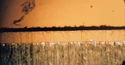
The importance of the stress raiser removal, before the bend test, has been addressed in most of the major international specifications such as National Standards of Canada5 and API6 (Fig. 5 - below).
Microscopic image (4x) is shown of the edge of a machined, internally FBE coated, sample from 12-in. OD pipe. The top section is the longitudinal view of the coating showing microcracks (Fig. 5).
The speed at which the bending is accomplished is also an important factor in determining the test results.
Most of the specifications and test procedures clearly specify the bending duration at which the test shall be completed. In general, the faster the bending is accomplished, the less the apparent flexibility of the coating.
Field bending
ANSI pipe code Nos. B31.8 and B31.4 outline the field bending details for uncoated pipe.7
According to B31.8, pipe sizes 12-in. and larger, the longitudinal axis of the pipe shall not be permanently deflected more than 1.5° for 1 pipe diameter length. As per B31.4, for pipe sizes smaller than 123/4 in. OD, the radius of the bend can be up to 18 PD.
There are two types of field pipe-bending machines: The tractor-bending shoe machine and the vertical hydraulic bending machine.8
The tractor-bending shoe machine is for fast, low-cost cold bending of pipe sizes 4-16 in. This machine can be easily mounted on side boom-equipped tractors for various sizes. Proper shoes having different dimensions are to be used with the corresponding pipe size.
On the other hand, the vertical hydraulic bending machine is more sophisticated and is capable of bending all grades of currently available API-5L pipe sizes 6-60 in. OD.
A comprehensive pipe-bending procedure for field construction is given in the 1989 CRC Evans Pipeline International Inc. catalog. According to this procedure, the pipe is loaded into the bending machine through the pin up shoe end (Fig. 6 [18234 bytes]) and the internal mandrel is driven into the pipe.
The pipe is positioned under the die where the bend is to start. The mandrel is then positioned inside and expanded. The pin up shoe and stiff back are raised simultaneously and the pipe is brought back into contact with the die.
To accomplish the bend, the stiff back is further raised to a predetermined point. This action accomplishes one "push." Then the pin up and the stiff back are lowered until the pipe contacts the roller, the pin up clamp opens automatically, the mandrel is contracted, and the pipe is moved one increment (bite) through the machine towards the pin up end position.
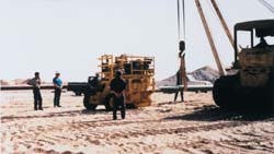
This completes one cycle or one bite. Several similar cycles may be needed to complete the bending operation to achieve the desired angle of deflection. Fig. 7 (below) shows the field bending of internally and externally FBE coated pipe in the Middle East.
An internally and externally FBE-coated pipe (8-in. OD) is being bent in the field (Fig. 7).
In Fig. 6 (representing a pipe in the bending machine), A and C are non-bent sections known as tangents. The length of the tangent will vary with pipe diameter.
For a 40-ft joint, less than 40 ft will be available for actual bending. The rest will remain as tangents. It is important that the tangent length be considered during calculations for the maximum bend for a specific pipe length.
The maximum possible bend may be even lower than the maximum allowed bend depending on the wall thickness, metal quality, type of the pipe (spiral, seamless, etc.), type of the die, skill of the operator, and the yield strength of the pipe.
At this stage, one should remember that the ANSI specified "maximum allowed bend" is for uncoated pipe. For coated pipes, additional restrictions apply based on factors affecting the flexibility of the coating. Unfortunately, this point can be overlooked while designing the pipelines that include field bending.
Field factors
Bite length, temperature of the pipe, flexibility of the coating, and the speed of the bending process are some of the major factors which affect the flexibility of the coating during field bending.
The flexibility values given in the coating's data sheets are based on coated specimens bent on a mandrel bend or four-point bending machine. The bend is continuous, and the total deflection is distributed equally throughout the bend length.
But the pipe in the field is bent in small increments ("bites") and the total angle of deflection is concentrated at this length instead of the full length.
Consider the following:
If a 15° deflection is required for a 40 ft, 24-in. OD pipe, and 10 ft is the tangent on each side, the total 15° deflection must be distributed on the remaining 20-ft length. That means, if the bite length is 2 ft, the deflection is 1.5° for each bite.
If the bite length is reduced to 1 ft, however, the deflection for each bite will be 0.75°. It is quite clear that for a continuous bend, a smaller bite length is required.
Using the same logic, for a bite length of 5 ft, the angle of deflection will be 3.75°. In field bending, it is possible to have this 3.75° deflection concentrated on a length smaller than 5 ft if the bend is not continuous.
It is reasonable to assume that when larger bite lengths are used during the field bend, the actual length where the deflection is distributed will be smaller than the bite length. This means that, because all the available length is not used for bending, the angle of deflection per pipe diameter length will increase for that bend and can go beyond the flexibility limit of the coating resulting in cracks and disbondment of the coating.
This can be confusing to field engineers who, with their own calculations, are well within the allowed bend for the particular joint of pipe. This was noticed during the field bending of 56 and 60-in. OD internally and externally FBE-coated pipe in the Middle East.9
Even though the total deflection obtained for a 40-ft joint was well below the 3°/PDL flexibility of the coating, the internal coating on several joints cracked and disbonded.
When the bite length was reduced to the minimum possible value, however, the cracks did not occur.
Temperature is another factor which controls the flexibility of the coating during field bending. That the coating is less flexible when the substrate is cold is often overlooked by many pipeline construction personnel in the field.
On several occasions, it has been observed that the internal coating which cracked when bent in the morning did not crack in the afternoon. Typical are observations made during construction of the previously cited FBE-coated pipe in the Middle East.9 It was noticed that the pipe bent in the morning (pipe temperature 4° C.) cracked, while pipe bent after 11 o'clock (pipe temperature 20° C.) did not crack.
Another important factor to consider is the elasticity of the pipe and the spring-back action during the bending process.
Depending on the yield strength, the pipe may have to be overbent substantially, sometimes by as much as two to three times more in order to obtain the desired permanent bend.
For example, if a total deflection of 6° is needed for a 20 ft piece of 24-in. pipe and 10 ft is used for tangents, then the 6° deflection is placed over 10 ft which will be 1. 2°/PDL, which is within the API limit.
If, however, because of the spring-back action of the pipe, it must be over-bent twice as much, this section has undergone a 12° deflection which is 2.4°/PDL.
It must be noted that in this case, even though the pipe will only be permanently deflected to 1.2°/PDL, it has to be temporarily deflected to 2.4°/PDL.
If the coating's maximum flexibility is only 2°/PDL under field conditions, the coating will then crack during bending because it has gone above its limit. Therefore, the spring-back action of the substrate must also be taken into account. This is critically important if the pipe is to be bent to the maximum limit of the coating's flexibility.
Consequences
Accurate information regarding the maximum extent to which the specified coating can be bent under field conditions is important to both design and construction engineers.
Only through accurate knowledge of the properties of the coating can the engineer design the pipelines which include bends, flanges, and other fittings with a certain degree of accuracy for the number of fittings. Designs based on incorrect information can be costly in either wasted money in materials or project time.
For the construction engineer, accurate information will translate into real savings through saved construction time. Pipe bending procedures based on incorrect flexibility values can create a pile of pipe with coating damages.
Acknowledgment
The author acknowledges the assistance of John D. Bethea, Herberts-O'Brien Inc., Houston, for technical discussions and Shibu P. Jacob and Mian Wagar Usman of Al-Qahtani Pipe Coating, Dammam, for microscopic evaluation of bend test samples.
References
1. Varughese, K., and Jacob, S.P., "Critical properties of protective coatings which affect corrosion prevention of underground pipeline," Seventh Middle East Corrosion Conference, Bahrain, February 1996.
2. Tenneco Gas Pipeline Group, Materials Management Department Guidelines Policy & Procedures manual, 5th Editioni, February 1988, p. 5.
3. Mobil USN & R Engineering Specification; Specification for Plant Application of Fusion Bonded 14 mil Epoxy pipe coating for land laid pipelines, October 1994.
4. Product Data Sheet, October 1983, 3M, Minneapolis.
5. National Standards of Canada, CAN/CSA-Z 245-20-M92 External Fusion Bonded Epoxy Coating for steel pipe, Section 12.11.2.
6. Recommended Practices for Unprimed Internal Fusion Bonded Epoxy Coating of line pipe, API Recommended Practice RP 5L7 (RP 5L7), Second Edition, June 30, 1988.
7. Pipeline Rules of Thump Handbook, Third Edition, 1993 E.W. McAllister, ed., Gulf Publishing Co., Houston.
8. CRC Evans Pipeline International Inc., Houston, 1989 catalog.
9. Al-Qahtani Pipe Coating Terminal, Field Construction Division, unpublished data, collected during the water injection pipeline construction, 1992, Saudi Arabia.
ABOUT THIS REPORT ...
The mechanical properties of pipeline coatings play a more important role in project economics than many design and construction groups recognize. The lead article of this year's Pipeline Report, the first in a series of two, addresses one of the properties, flexibility. Also covered in this report are an automated, time-saving tank cleaning system and high pressure polyethyene pipe.
The Author
Kuruvila Varughese is product manager for the functional coatings group of Herberts-O'Brien Inc., Houston, wholly owned subsidiary of Hoechst AG. Previously, he worked as director of research and development and technical service departments of Al-Qahtani Pipe Coating Terminal, Dammam, Saudi Arabia. Varughese has also worked as a research chemist at Rice University, Houston, Napko Paints & Coatings Co., Houston, and Forsyth Research Center, Boston. Varughese holds a BS in chemistry from Kerala University and an MS in physical chemistry from Bombay University. He is a member of NACE, American Water Works Association, and the New York Academy of Sciences.
Copyright 1996 Oil & Gas Journal. All Rights Reserved.


