High winter gas demand met by Michigan's Blue Lake storage
Edward R. Scarpace
ANR Storage Co.
Detroit
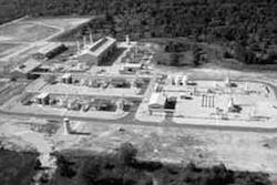
ANR Storage's Blue Lake 18A fully automated compressor building and gas plant operate 24 hr a day (Fig. 1).During February 1996, ANR Pipeline Co., Detroit, used its capacity in the recently completed Blue Lake 18A natural-gas storage field to meet record gas demand in the Midwest market area.
The severity of the winter weather in the U.S. Midwest is best illustrated by the high temperature of 1° F. in Milwaukee, Wis., for Feb. 2, 3, and 4. The low temperatures those days were, respectively, -20° F., -26° F., and -19° F.
ANR (ANR Pipeline Co. and ANR Storage Co.) met demand by withdrawing 2.8-3 bcfd from storage and utilizing the Blue Lake facility to the maximum extent possible. Although only one of 21 fields ANR operates in Michigan, Blue Lake supplies 18% of the company's total storage volume and 21% of the daily gas from storage.
In its third year of operation, this facility experienced record gas withdrawals, over 94% of the volume, during the demanding 1995-96 winter withdrawal period.
The Blue Lake gas-storage field, with 46 bcf of working gas and 7.5 bcf base gas, is the largest combination gas-storage withdrawal/refrigeration processing plant in the U.S. Daily throughput can reach 690 MMscfd.
The facility is fully automated and operated around the clock by only two shifts of three employees. Fig. 1 shows the Blue Lake compressor station including the gas-processing facilities.
The high working gas-to-base gas ratio is possible because of the excellent porosity and permeability of the Salina-Niagara pinnacle reef storage reservoir and its favorable geologic characteristics. These allow it to be operated up to 32% above the initial discovery pressure, to 4,020 psig wellhead.
Blue Lake-18A gas storage project was initially designed for 600-MMscfd gas withdrawal during the fall and winter months, but peak withdrawal has been tested and operated at intervals at up to 690 MMscfd during the 3 years of initial operation.
Gas injection for the entire operating range is an average of 230 MMscfd during the spring and summer months. The total project capital cost was $115 million. Construction for this project was completed under budget and was started up ahead of schedule.
To meet the high gas demand for winter heating, a state-of-the-art gas storage facility and gas-processing plant was installed.
The totally automated controls system, the extensive and accurate surface facilities and reservoir design, the experienced project management team, and the engineering enhancements since the first gas withdrawal in the 1993-1994 winter contributed to the successful gas-storage operation.
Improvements
ANR's system storage was drawn down to near base-gas levels in the 1995-1996 winter, as shown in Fig. 2A [48691 bytes]. The prolonged winter caused most of the low storage balance, but not completely filling storage in the fall of 1995 contributed to these low working-gas volumes in March of 1996.
Blue Lake's percentage contribution to ANR's daily peak gas withdrawal is shown in Fig. 2B.
Blue Lake's reliable operation was enhanced by some engineering improvements installed after the first year of operation. These enhancements were mostly in heat tracing pipes, tanks, and other equipment containing brine that has less salt concentration than anticipated.
Specific improvements included preheating the rich ethylene glycol returning to the glycol-regeneration unit; heat tracing additions to some liquid control valves and associated piping; and drying of flash gas from the glycol-regeneration unit so it can be utilized as fuel.
They also included heat tracing and insulation of a recovered-water storage tank; modification of an automatic electric-power transfer switch; and installation of isolation valves under some skid-mounted pressure relief valves so they could be tested in place.
And they included installation of a monorail and winch to provide maintenance for some hydrocarbon liquid pumps; modification of some pipe supports to minimize vibrations; installation of some access platforms to enhance maintenance of valves; and installation of emissions-monitoring test points on compressor engines, generator engines, and withdrawal-gas heater stacks.
Capital cost of the improvements was small at about $320,000 compared to a $66 million compressor station/gas processing plant.
Depleted gas field
The Blue Lake-18A gas storage field is about 250 miles northwest of Detroit in Kalkaska County, Mich. This project is owned by Blue Lake Gas Storage Co., a partnership of subsidiaries of ANR Storage Co. (ANRS), a subsidiary of Coastal Corp. and MCN Corp. ANRS is the operator.
Because of the reservoir properties in Michigan, ANR currently operates 20 other storage fields there. Including Blue Lake, the total working storage volume is almost 250 bcf.
MCN subsidiaries operate six storage fields with about 140 bcf working storage volume. ANRS has also developed storage fields in other states.
The Blue Lake-18A gas- storage field is a depleted retrograde-condensate gas field. More than 1 million bbl of natural-gas condensate were produced with the gas during the primary production. The storage operation will mobilize a similar amount of hydrocarbon condensate over the next 20 years and will withdraw this condensate with the gas.
The presence of hydrocarbon condensate in the reservoir complicates the engineering, construction, and operation of the gas-storage facility. Removal of the condensate and water from the gas during gas withdrawal is paramount to achieve pipeline-quality gas.
The Blue Lake-18A gas-storage project consists of: 46 bcf working-gas reservoir; 14 injection/withdrawal wells directionally drilled into the 6,600-ft deep reservoir; two 4,200 psig rated 20-in. diameter gathering headers with a total length of 2.4 miles; a self-contained 18,000-hp compressor station/gas-processing facility; and a 2.3 mile, 30-in. pipeline to connect the compressor station to an existing ANR transmission pipeline.
ANRS was the project manager and coordinated engineering and construction. In addition to being the largest developed by ANR, this was a fast-track project.
It was identified in February 1991 as being required to meet winter peak gas demands for the 1993-1994 heating season. This meant that engineering, procurement, and construction would have to be completed in 25 months to start injection so that withdrawal could begin in November 1993.
Construction
Preliminary process engineering, layout, and cost estimates were immediately started in-house at ANRS, with detailed process design and preparation of piping and instrumentation diagrams (P&IDs) performed by outside engineering contractors.
Simultaneously, the environmental studies necessary for a U.S. Federal Energy Regulatory Commission (FERC) filing were performed. All of the preliminary engineering was completed for an August 1991 FERC application filing.
ANRS, meanwhile, was preparing equipment specifications to bid and purchase the long-lead major equipment, including three 6,000-bhp integral engine-compressor units, gas coolers, vessels, high-pressure gas pipe, valves, and the gas-processing equipment.
ICF Kaiser Engineers, Oakland, Calif., was selected to complete the detailed engineering and construction drawings utilizing an Integraph 3D CAD system.
A detailed engineering and construction plan was enacted to split the construction into packages by discipline so that civil and foundations could be immediately started in spring 1992 when a FERC construction permit was expected.
Engineering would continue with the mechanical and electrical drawings until the foundations were 20% complete. The mechanical construction package would then be bid followed by the electrical package.
The necessary FERC and State of Michigan air-emission construction permits were received later than planned so that ground was broken on June 1, 1992. Devere Construction, Alpena, Mich., completed all of the civil work, foundations, and office building interior.
Three mechanical contractors were utilized: Welded Construction, Perrysburg, Ohio, for the pipeline and gathering system; Bishop Corp., Tulsa, and R.L. Morris, Kalkaska, Mich., for the compressor station.
Two electrical contractors, Newkirk Electrical, Manistee, Mich., (compressor station) and Swan Electric, Lansing, Mich., (gathering system) were used. Building manufacture was awarded to Siscorp, Houston.
During the winter peak, there were about 300 construction workers daily on site. In addition, there were more than 50 other personnel, including ANRS engineers and field project managers, ICF Kaiser construction administration and engineers, field inspectors, radiographers, and miscellaneous service personnel.
The construction on the 20 acre compression-station site included 6,000 yd of concrete, 230,000 weld in. of piping installation and more than 500,000 labor man-hr.
The ANRS project-management team coordinated 57 outside-contracting companies for installation services associated with the compressor station, gathering system, and pipeline. An additional 46 contractor companies were utilized for various portions of well drilling and completions.
This effort of the engineering, construction, project management, and support personnel allowed gas to flow into the storage reservoir on Mar. 30, 1993, two days ahead of schedule, and 302 days after ground was broken.
Construction of the gas-withdrawal facilities continued through the summer of 1993 to meet a November withdrawal schedule.
Major systems
The Blue Lake compressor station is a self-contained facility, generating its own electric power and providing all utilities and support functions.
The major systems at the Blue Lake station include:
- Gas-injection compression to 4,200 psig
-Single and two-stage compression with intercooling
-Support auxiliaries for the engine-compressors
-Station fuel-gas conditioning and regulation
- Emergency shutdown
-Isolation and venting compressor area piping
-Isolation and venting gas-processing area piping
-Gas-detection system
-Fire-detection system
- Gas metering
-Separation before one-way gas metering
-Custody transfer running with dual flow computers
- Gas withdrawal
-Separation of free liquids
-Gas heating
-Ethylene glycol injection to adsorb water
-Pressure reduction
-Separation of hydrocarbons and water from gas
-Secondary cooling at medium pressures
-Refrigeration cooling at low pressures
-Gas compression into the pipeline at low pressures
- Hydrocarbon condensate pumping and metering
-Collection and stabilization of condensate
-Pumping and metering into a hydrocarbon pipeline
-Vapor recycle compression of flash gas
- Station support
-Electric power generation (2,400 kw)
-Air compression and dryer systems
-Hot water heating
-Ethylene glycol-regeneration system
-Hydrocarbon and brine drain and storage system
-Waste oil drain and storage system
-Lube oil and glycol storage systems
- Station control system
-Central controlled programmable logic controller (PLC) system
-Instruments hard wired to input/output (I/O) cabinets
-Cabinets connected to PLCs by coaxial cable.
Fig. 3 [23699 bytes] presents a flow schematic of the Blue Lake compressor station.
Control system
All of the equipment at the Blue Lake facility is controlled and monitored by two Allen Bradley Model 5/60 PLCs. One of the units is an on-line spare that automatically takes over upon failure of the other PLC.
The control system includes wiring of about 3,000 field-located instruments to 10 strategically located I/O cabinets in the 20-acre site, or to PLCs associated with control panels near the three engine-compressor units, the three engine-generator units, the two propane compressors, the glycol-regeneration skid, the vapor-recycle compressor skid, and the two withdrawal- gas heaters.
Coaxial cable connects the I/O cabinets and major equipment PLCs to the PLCs located in the control room inside the auxiliary building. There are three operator-interface units to monitor the equipment and processes and to change the set points of control loops.
The control system performs parametric emission monitoring of the engine-compressor and engine-generator units. Control programs were developed to calculate emissions of nitrogen oxides and carbon monoxide based on the measured engine operating parameters such as fuel flow, air-manifold pressure, and air-manifold temperature.
The control system also provides record keeping and trending of values of any equipment item or process desired. The system also transmits data over the ANRS supervisory control and data acquisition (scada) system to the northern Michigan office and to Detroit.
The computer system was set up to control remotely the station from either of the northern Michigan office or from Detroit and to shut it down safely upon malfunction.
Because this facility is critical to ANRS system's gas withdrawal, however, and because of the lengthy time it would take to restart it, remote control is not used.
The control system installed using the PLCs and I/O cabinets with interconnecting coaxial cable was significantly less expensive to construct, especially considering the widespread 20-acre site required by the process equipment.
Gas-injection compression
Three identical Dresser-Rand 6,000-hp integral gas engine-driven compressor units are installed at the Blue Lake-18A compressor station for both gas injection and withdrawal.
The compressors were designed and installed to permit single-stage operation with all six compressor cylinders in parallel to 1,400 psig; and two stage-operation using three first-stage cylinders to 1,400 psig and three second-stage cylinders to 4,200 psig.
Dresser-Rand manufactured special second-stage cylinders for the 4,200-psig injection service at Blue Lake, using a design ANRS has operated in gas storage for the past 16 years. The manufacturer modified the pattern of the shorter stroke cylinders previously marketed for the Ingersoll-Rand KVR engine-compressor units. This proven design has reduced maintenance costs for the compressors.
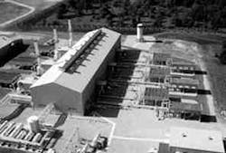
Fig. 4a [48691 bytes] shows the engine-compressor units inside the compressor building. Fig. 4b [48691 bytes] presents a close-up of one of the engine-compressor units showing the second-stage cylinders.
The compressors are equipped with a two-bottle pulsation suppresser/acoustic filter system on both the suction and discharge of each stage of compression. An extensive analog was performed at Southwest Research Institute, San Antonio, over the entire compression range to minimize pulsations and vibrations.
The compressor-discharge piping for both compression stages used induction bends and extruded headers to minimize field construction time and to lower construction costs associated with welding the heavy-wall pipe fittings.
The gas-compressor discharge piping (shown adjacent the compressor building) used induction bends and extruded headers to reduce construction time and lower costs (Fig. 5).
Fig. 5 presents a view of the outdoor gas compression piping and equipment.
Additional special auxiliaries associated with the engine-compressor units include: hospital-grade mufflers, low-speed fans on all gas and jacket water coolers to minimize noise, personal computer-based control panels, and a parametric monitoring system to limit automatically engine operation to speeds and loads that result in low engine emissions.
One of the lean-burn engine compressors, which already conformed to best available control technology (BACT), also is equipped with an oxidation-type catalytic converter on the exhaust system, downstream of the turbocharger and upstream of the muffler.
This catalytic converter is installed as part of a test to determine the effectiveness of an oxidation catalyst at the low exhaust temperatures (about 500° F.) on CO and VOC emissions.
Gas withdrawal
The gas-withdrawal system consists of the equipment necessary to process the gas from the storage reservoir into pipeline-quality gas flowing into ANR's transmission system.
At Blue Lake, this equipment is complex because of the wide operating range of the reservoir (wellhead flowing pressures of 4,020 psig to 300 psig) and the heavy hydrocarbons, brine, and water vapor in the withdrawal gas from the wells.
The process design dictated that the gas must be refrigerated to 0° F. to result in pipeline-quality gas that would meet customers' requirements.
The high gas-withdrawal rates and the requirement to operate at turndown of 25% of maximum rates identified the need for installing two identical trains of equipment. The wide operating pressure range caused equipment to be installed that is only used for part of the withdrawal operation.
The location of the storage field, with its low ambient temperatures during the winter, and the high reservoir pressures, helped minimize the cost to refrigerate the gas.
The low temperatures necessary for condensation of the heavy hydrocarbons from the gas could be achieved most of the gas-withdrawal season by cooling because of the Joule-Thomson effect of pressure reduction and supplemented by cooling with cold ambient air.
Pipeline-quality gas
Each gas-withdrawal equipment train, sized to remove heavy hydrocarbons, brine, and water vapor from 300-350 MMscfd gas, includes: a field inlet separator, a withdrawal-gas heater, a first-stage pressure reduction valve manifold, a primary-gas separator, a withdrawal gas cooler, a gas-to-gas exchanger, a low-temperature separator, a propane chiller, a second-stage pressure reduction valve manifold, and a final separator.
Fig. 6 [30192 bytes] presents the process flow of gas-withdrawal equipment for one train.
The field inlet separator is a 42-in. OD x 19-ft seam-to-seam vertical centrifugal scrubber designed for a maximum working pressure of 4,200 psig. This special high-efficiency separator was designed and manufactured by National Tank Co., Tulsa, under license from Gasunie Research N.V, Amsterdam.
Brine and lubricating oil are separated from the gas in this vessel to prevent contamination of the ethylene glycol that is injected into the gas for freeze protection.
At high gas-reservoir flowing pressures, 4,020 psig down to about 2,700 psig, the Joule-Thomson cooling is greater than the requirements to condense heavy hydrocarbons from the gas.
Consequently, after flowing through the field inlet separator, the gas is heated in the withdrawal gas heater (a forced-draft 16 million BTU/hr unit manufactured by Sivalls Inc., Odessa, Tex.) to control the gas temperature downstream of the first-stage pressure reduction valve to 0° F.
The first stage pressure-reduction valve is a 12-in., 2,500 lb ANSI low-noise valve manufactured by Continental Components Inc., Mission Viejo, Calif. A 65% ethylene glycol stream is injected into the gas upstream of the first stage pressure-reduction valve to absorb water vapor from the gas and to melt hydrates formed at these low temperatures.
The hydrocarbons condensed as a result of this cooling are separated from the gas in the primary separator. This separator is 84-in. OD with 32 ft seam to seam and contains an inlet diffuser, internal weir, and vane mist extractor.
The internal weir is utilized to keep the ethylene glycol and water layer at the bottom of the vessel from flowing into the end boot of the vessel. The ethylene glycol and water flows out the vessel bottom on interface level control.
The hydrocarbon liquid layer that floats on the ethylene glycol layer flows over the top of the weir and into the end boot of the vessel. The hydrocarbon liquid flows out of the vessel on level control.
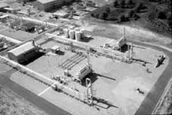
Downstream of the primary separator are the withdrawal-gas heaters and the field inlet separators, along with the station gas-flow meters (Fig. 7).
The equipment downstream of the primary separator only plays a supporting role when the reservoir flowing pressure is greater than 2,700 psig. Fig. 7 shows the withdrawal-gas heaters and the field inlet separators, along with the station gas-flow meters.
At less than 2,700 psig, the heater is shutoff when the downstream gas temperature, as a result of Joule-Thomson cooling, would be greater than 0° F.
In addition, a two-stage pressure reduction is required along with additional cooling in the gas-to-gas exchanger to achieve the 0° F. dew point.
The first-stage pressure reduction valve is operated on pressure control with a downstream pressure set point of about 1,400 psig. The coincident temperature reduction results in the gas temperature being about 18° F.
Gas at 18° F. and 1,400 psig from the outlet of the primary separator flows through the tubes of the gas-to-gas exchanger where it is cooled with 0° F. gas in the exchanger shell.
Hydrocarbons condensed as a result of this cooling are removed in the low-temperature separator. This vessel is identical in size, pressure rating, and internal design to the primary separator.
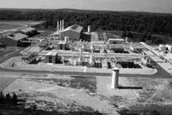
The gas-withdrawal separation and cooling equipment yield condensed hydrocarbons (Fig. 8).
Additional gas cooling takes place as a result of the pressure reduction through the second-stage pressure reduction valve. The condensed hydrocarbons from this gas cooling are removed in the final separator. Fig. 8 shows the gas-withdrawal separation and cooling equipment.
Well flowing pressures between 1,500 psig and 1,000 psig require additional cooling to achieve the desired gas dew point. This additional cooling is achieved by an aerial cooler (withdrawal-gas cooler) rated at 13 million BTU/hr.
It uses six 20-hp fans to provide the gas cooling. These well flowing pressures occur during February when ambient temperatures in northern Michigan average 10-15° F. Then the small pressure reduction coincident cooling through the second-stage pressure-reduction valve with back exchange will result in 0° F. gas in the final separator.
At well-flowing pressures of less than 1,000 psig, the propane chiller is used in series with the withdrawal gas cooler and the gas-to-gas exchanger to achieve the 0° F. temperature in the final separator.
A 320-ton capacity propane refrigeration screw-type compressor and condenser system provides the liquid propane required in the chiller for this cooling.
In addition to the gas-processing, low gas-withdrawal pressures (300-900 psig) require gas compression to boost the pressure to pipeline pressures.
The conceptual design of the Blue Lake gas-storage field by ANRS included extensive optimization studies to determine the lowest unit cost for gas-storage service, balancing capacity, base gas, number and type of wells, and surface facilities.
Multiple conceptual designs and cost estimates led to the conclusion that the larger capacity of the field, achieved by over pressure of the reservoir and minimizing base gas and accompanied by high-capacity horizontal wells and extensive surface facilities, was the most economical alternative for development.
The Author
Edward R. Scarpace is director of facility development for ANR Storage Co., Detroit. He has been with ANR Storage for the past 16 years as manager of facilities engineering (1980-1992) and as director for engineering and construction (1992-1996). He has also worked for Shell Chemical Co. as a process engineer, Aramco as supervisor of commissioning based in Abqaiq, Saudi Arabia, and as senior project engineer for Lawrence Allison & Associates. Scarpace holds a BS (1967) from San Jose State University, is a member of the Engineering Society of Detroit, and is currently first vice-chairman of the compressor committee for AGA.
Copyright 1996 Oil & Gas Journal. All Rights Reserved.


